
Paste patterns formation method and transfer film used therein

a transfer film and pattern technology, applied in the manufacture of electrode systems, cold cathode manufacturing, electric discharge tube/lamp manufacture, etc., can solve the problems of low production efficiency, decrease in electrical conductivity of electrode patterns, and large dot pitch, so as to achieve high aspect ratio, not easy to produce, and easy to produ

Inactive Publication Date: 2010-06-29
EI DU PONT DE NEMOURS & CO
View PDF30 Cites 10 Cited by
  • Summary
  • Abstract
  • Description
  • Claims
  • Application Information

AI Technical Summary

Benefits of technology

The present invention provides an inexpensive method for forming a paste pattern with a high aspect ratio that is easy to produce and maintains its properties. The method involves creating a transfer pattern on a film base material, transferring it onto a substrate, and then applying a paste into the transfer pattern depressions. The transfer pattern can be created using laser, photoetching, or press stamping methods. The invention also includes a transfer film with a transfer pattern depression for use in the method.

Problems solved by technology

The ability to easily produce patterns having a high aspect ratio is an important issue common to these applications.
However, reduction in the cross-sectional area of the electrode pattern causes a decrease in electrical conductivity of the electrode pattern.
In PDP, if the barrier ribs are too wide, the dot pitch becomes large and it is not possible to achieve high resolution.
In the case of screen printing, however, since there are limits on the amount of paste that can be coated in a single coating, in order to form a pattern of adequate thickness; it is necessary to repeatedly print the paste many times. In addition, in the case of printing several times, it is difficult to position the coating paste with high precision each time.
However, processes using photosensitive paste require an expensive investment with respect to the mask, developing apparatus and so on, and production costs tend to be high.
In addition, since the electrically conductive or insulating fine powder contained in the paste is optically opaque, random reflection occurs within the paste composition during exposure when the coating thickness is increased, thereby preventing light from adequately reaching deep portions of the paste.
Consequently, it is difficult to obtain a pattern of high aspect ratio simply by using a photosensitive paste and developing directly.
Moreover, since photosensitive paste has poor storage stability, control and transport of materials is bothersome.
However, in the case of using an adhesive layer, not only is there the added step of forming the adhesive layer, there is also the risk of the adhesive layer components diffusing into the pattern, as well as a decrease in electrical conductivity or other predetermined pattern properties.
In addition, in the case of blending a pressure-sensitive adhesive component into the pattern, it is difficult to select a preferable pressure-sensitive adhesive component so that the required properties of the pattern do not decrease due to the addition of the pressure-sensitive adhesive component.
Moreover, as is described in this document, in the case of transferring to a substrate following pattern formation, there is the risk of the pattern itself being deformed or the desired aspect ratio being unable to be obtained due to pressure applied to the pattern during transfer.

Method used


Image

  • Paste patterns formation method and transfer film used therein
  • Paste patterns formation method and transfer film used therein
  • Paste patterns formation method and transfer film used therein

Examples


example 1

Production of Black Paste for Transfer Film

[0072]35 parts of polyvinyl alcohol resin PVA #500 (Kanto Chemical) were added to 65 parts of ion exchange water heated to 90° C. in a stainless steel container, and then dissolved by stirring for 2 hours. Next, after cooling the solution to room temperature, 15 parts of glycerin (Kanto Chemical) were added and stirred for 5 minutes. Next, 20 parts of a commercially available Indian ink (Kuretake, BA7-18) were added followed by stirring for 5 minutes to obtain a black paste-like PVA solution. Finally, this PVA solution was transferred to a plastic container and allowed to stand overnight to obtain a black paste for a transfer film.

[0073](Production of Transfer Film)

[0074]Using a TEFLON (registered trademark) 500 PFA film (available from E.I. du Pont de Nemours and Co.) for the film base material (film thickness: 125 μm), the black paste was coated thereon using a doctor blade method. Next, the coated paste was dried for 10 minutes in an ove...

example 2

Separation of Transfer Film: Hot Water Dissolving Method

[0082]A substrate having a transfer pattern depression filled with paste produced using the same method as Example 1 was heated for 10 minutes on a hot plate at 130° C. followed by removing from the hot plate and allowing to stand until it returned to room temperature. Next, the substrate with transfer pattern material was immersed for 10 minutes in hot water at 80° C. followed by ultrasonic treatment for 30 seconds using an ultrasonic cleaner. Subsequently, the substrate was removed from the hot water and washed with running water at 40° C. As a result, only the paste pattern of the embedded silver paste remained on the substrate. The shape of the resulting paste pattern was 70 μm wide and 60 μm deep. As noted previously, the aspect ratio has no upper limit, however in this example the aspect ratio was 6 / 7.

[0083]As has been described above, a paste pattern having a high aspect ratio (6 / 7) was also able to be formed easily usin...


PUM

PropertyMeasurementUnit
thicknessaaaaaaaaaa
temperatureaaaaaaaaaa
thicknessaaaaaaaaaa

Abstract

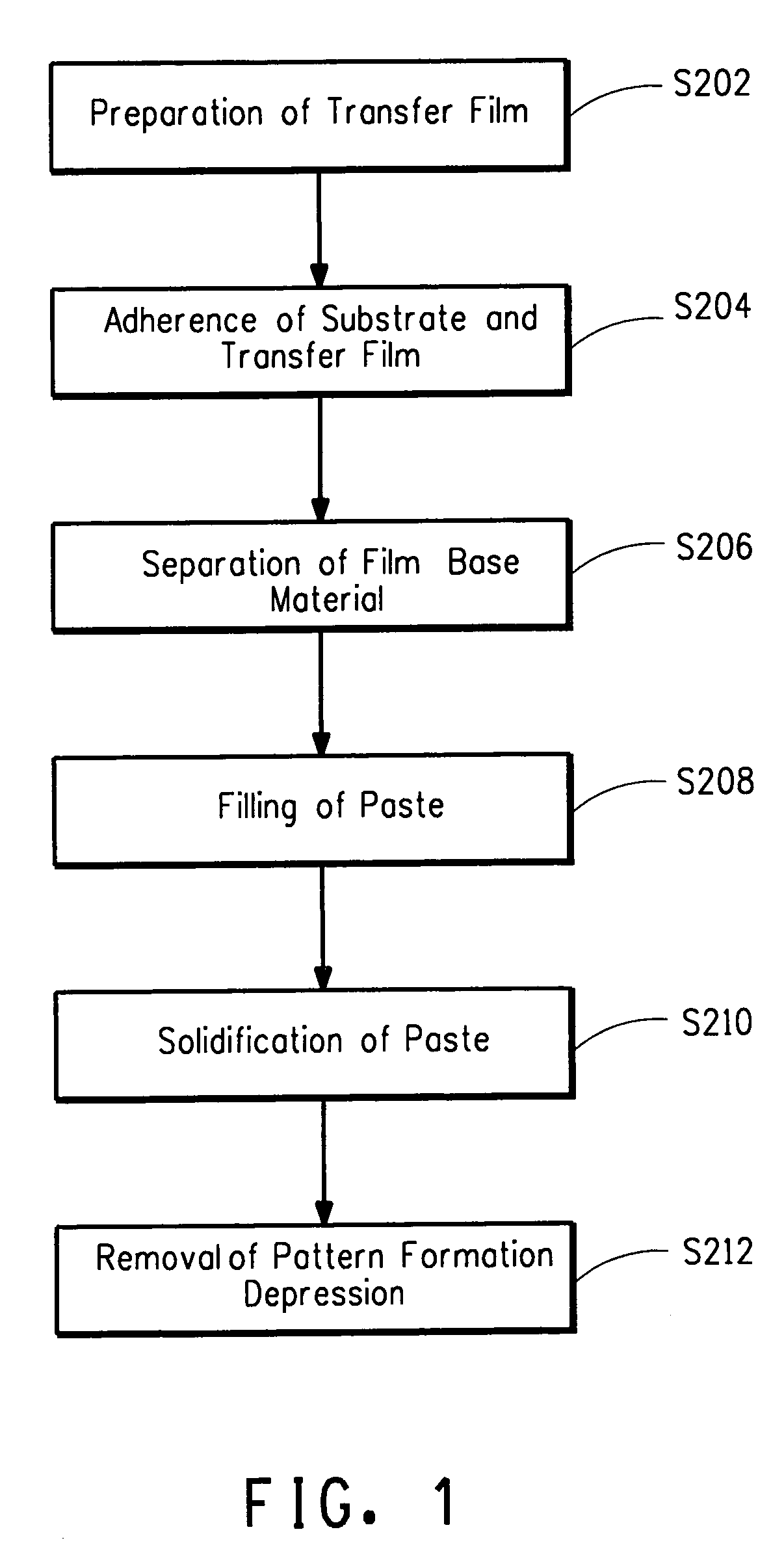
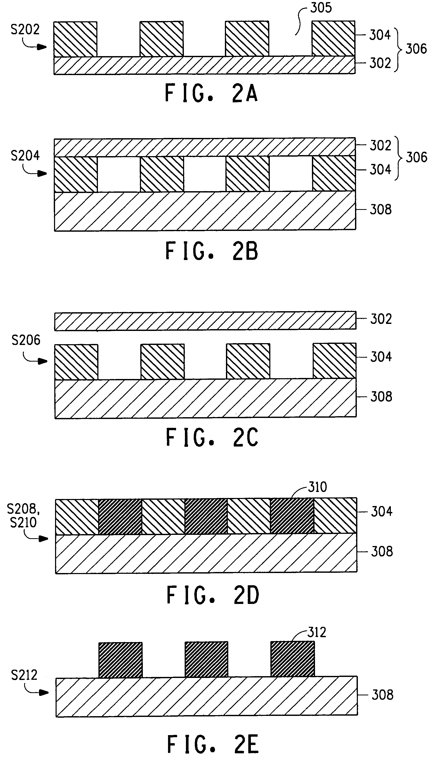
Disclosed is a paste pattern formation method comprising the steps of: forming a transfer pattern material on a film base material to prepare a transfer film; sticking the transfer film on a substrate on which a transfer pattern is formed so that the transfer pattern material contacts the substrate; separating the film base material from the transfer pattern material; filling a paste into the transfer pattern depression; solidifying the paste; and removing the transfer pattern material.

Description

BACKGROUND OF THE INVENTION[0001]1. Field of the Invention[0002]The present invention relates to a paste pattern formation method. More particularly, the present invention relates to a paste pattern formation method for forming a paste pattern having a high aspect ratio. The present invention also relates to a transfer film used in this paste pattern formation method.[0003]2. Description of the Related Art[0004]Various types of patterns are formed in electrical devices. For example, predetermined electrode patterns are formed on the top and bottom surfaces in solar cells. In addition, predetermined wiring patterns are formed on a substrate in wiring boards. Moreover, patterns of barrier ribs for separating each dot, address wires, electrodes and so on are formed in plasma display panels (PDP).[0005]The ability to easily produce patterns having a high aspect ratio is an important issue common to these applications.[0006]With respect to the electrode patterns of solar cells, it is pre...

Claims


Application Information

Patent Timeline
Patent Type & Authority Patents(United States)
IPC IPC(8): B44C1/175B32B37/06B32B37/12B32B37/02B29C65/54B44C1/22B32B38/04B32B37/04B32B38/18B29C65/56B23K26/36
CPCH01J9/02H01J9/24H01L31/022425H05K3/1258H01J2211/36H05K2203/0537Y10T428/24479Y02E10/50Y10T428/1073Y10T428/24802Y10T428/1005Y10T428/10Y10T428/1059H05K2203/0568C09K2323/02C09K2323/05C09K2323/055C09K2323/00H01J11/44
Inventor AKIMOTO, HIDEKI
Owner EI DU PONT DE NEMOURS & CO
Learn More