

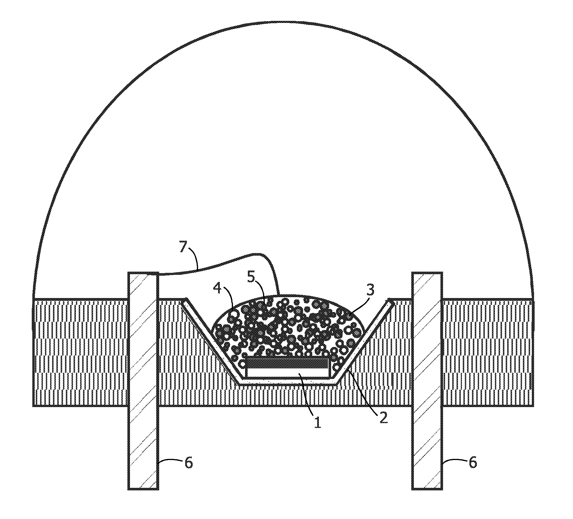
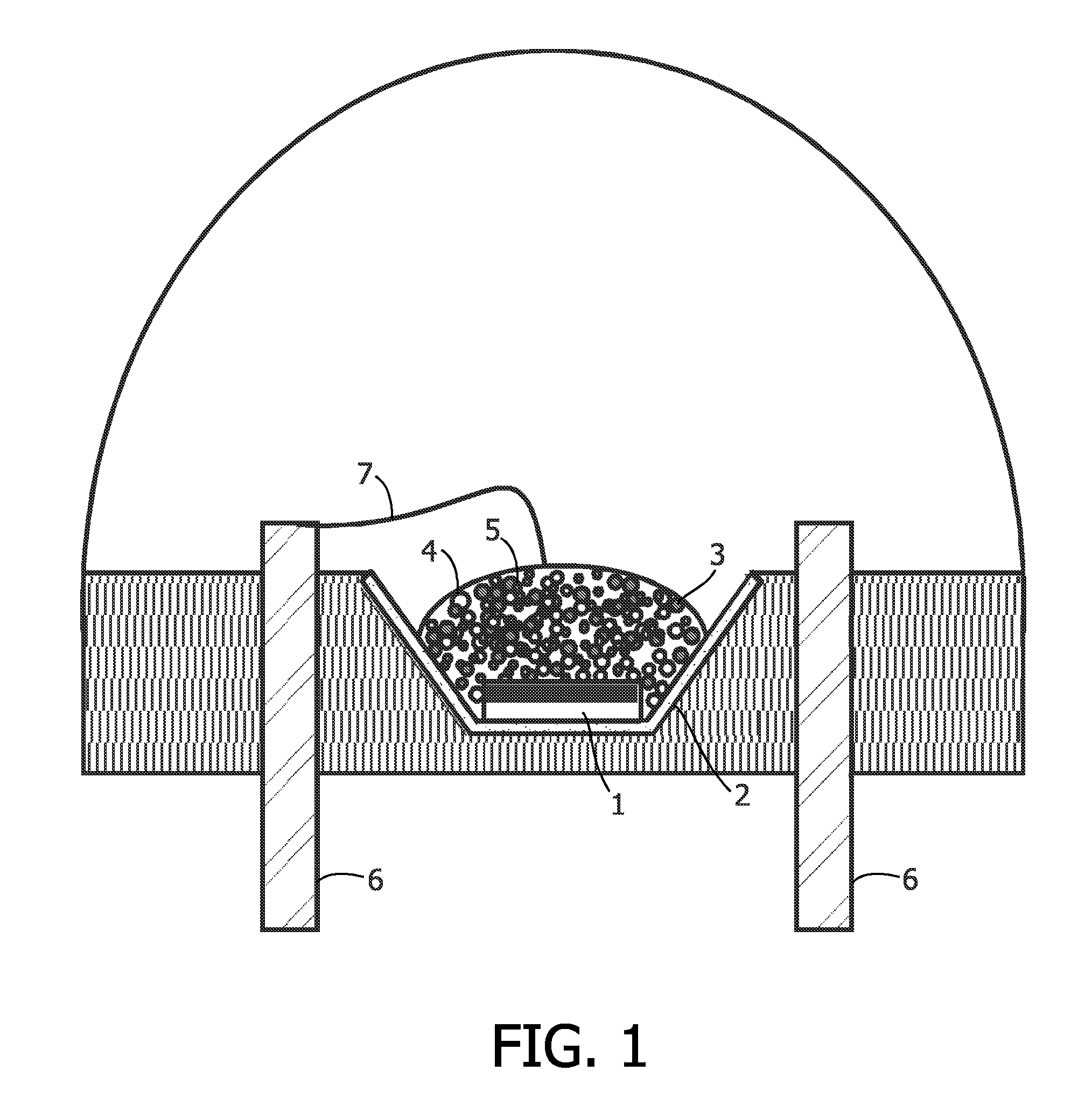
Illumination system comprising color deficiency compensating luminescent material
a luminescent material and color deficiency technology, applied in the direction of discharge tube/lamp details, discharge tube luminescnet screens, lighting and heating apparatus, etc., can solve the problem of unnatural pinkish light, limitation of such phosphor-convertible light-emitting devices, and inability to generate white light of the desired tone, etc. problem, to achieve the effect of improving color rendering and low color temperatur
- Summary
- Abstract
- Description
- Claims
- Application Information
AI Technical Summary
Benefits of technology
Problems solved by technology
Method used
Image

Examples
specific embodiments
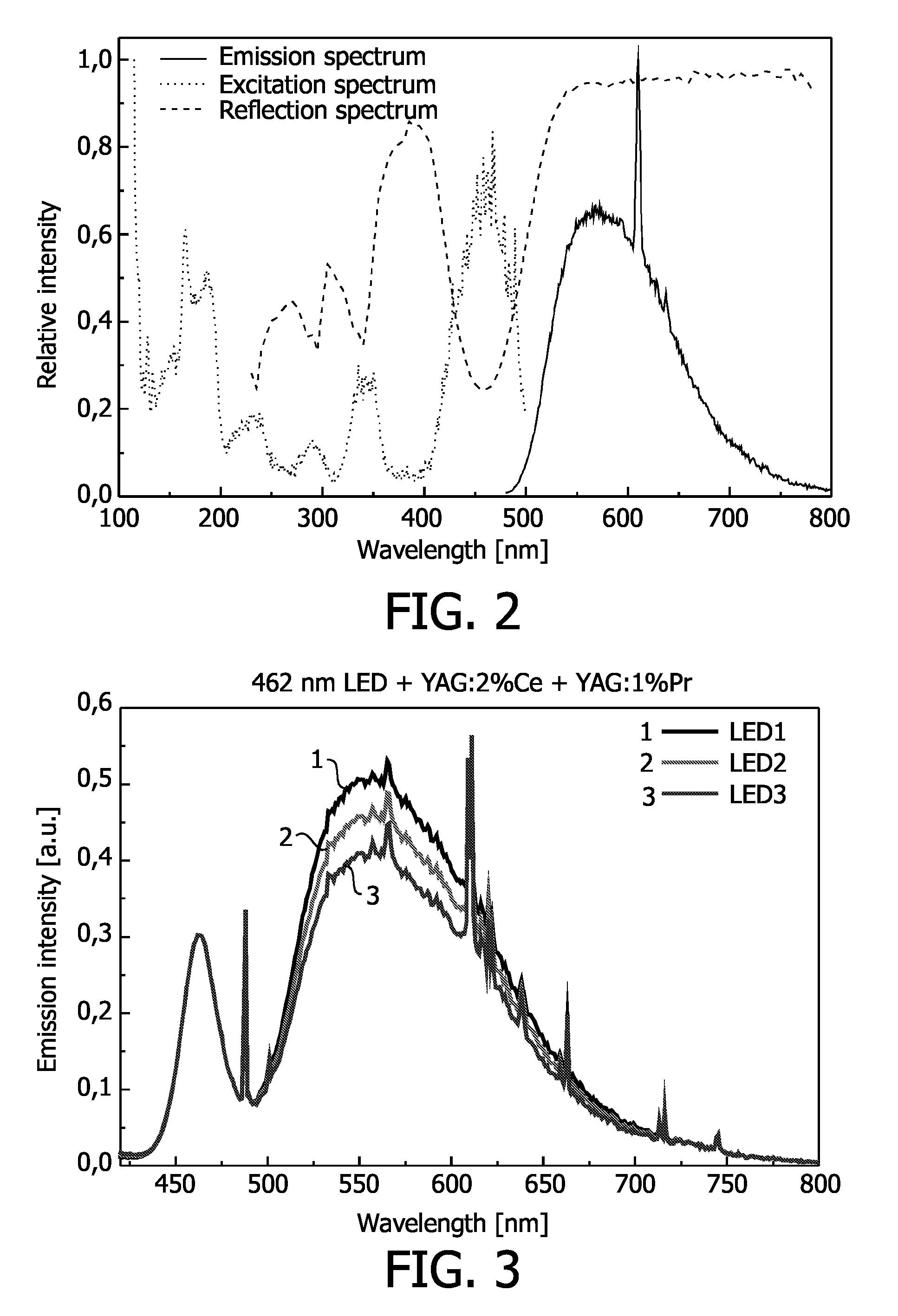
1. White LED Comprising YAG:2% Ce and YAG:1% Pr
[0073]A phosphor blend of 70 to 80% YAG:2% Ce and 20 to 30% YAG: 1% Pr was suspended in a silicone precursor, a polymerization catalyst was added, and a droplet of this suspension was deposited onto the LED die, based on a 460 nm emitting InGaN. A plastic cap sealed the LED and the silicone was polymerized within about an hour. The spectra of LEDs with three different coating thicknesses are depicted in FIG. 3.
2. White LED Comprising (Y,Gd)AG:2% Ce and (Y,Gd)AG:1% Pr
[0074]A phosphor blend of 70 to 80% (Y,Gd)AG:2% Ce and 20 to 30% (Y,Gd)AG:1% Pr was suspended in a silicone precursor, a polymerization catalyst was added, and a droplet of this suspension was deposited onto the LED die, based on a 460 nm emitting InGaN. A plastic cap sealed the LED and the silicone was polymerized within about an hour. The spectra of LEDs with two different coating thicknesses are depicted in FIG. 4.
[0075]According to a further aspect of the invention, in a...
PUM
 Abstract
Description
Claims
Application Information