Multi-mode switching control circuit and method for improving light load efficiency in switching power supplies
a control circuit and power supply technology, applied in pulse manipulation, pulse technique, instruments, etc., can solve the problems of imposing emi problems, high-gain, high-bandwidth, low-offset differential amplifiers,
- Summary
- Abstract
- Description
- Claims
- Application Information
AI Technical Summary
Benefits of technology
Problems solved by technology
Method used
Image
Examples
Embodiment Construction
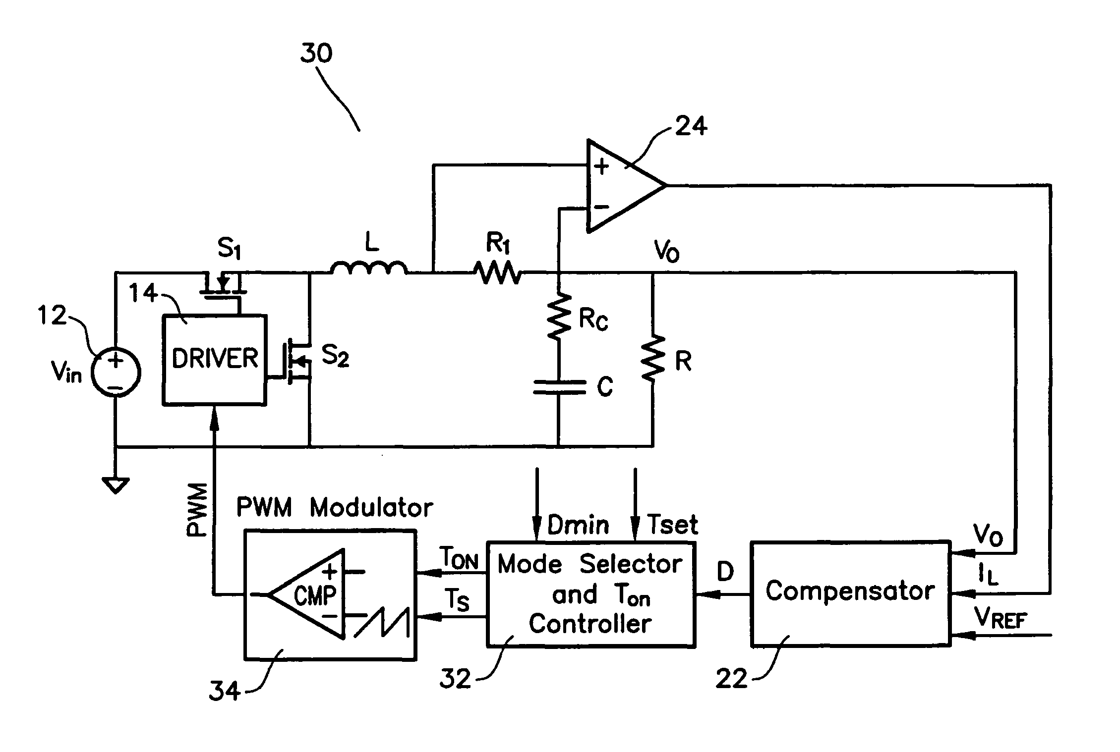
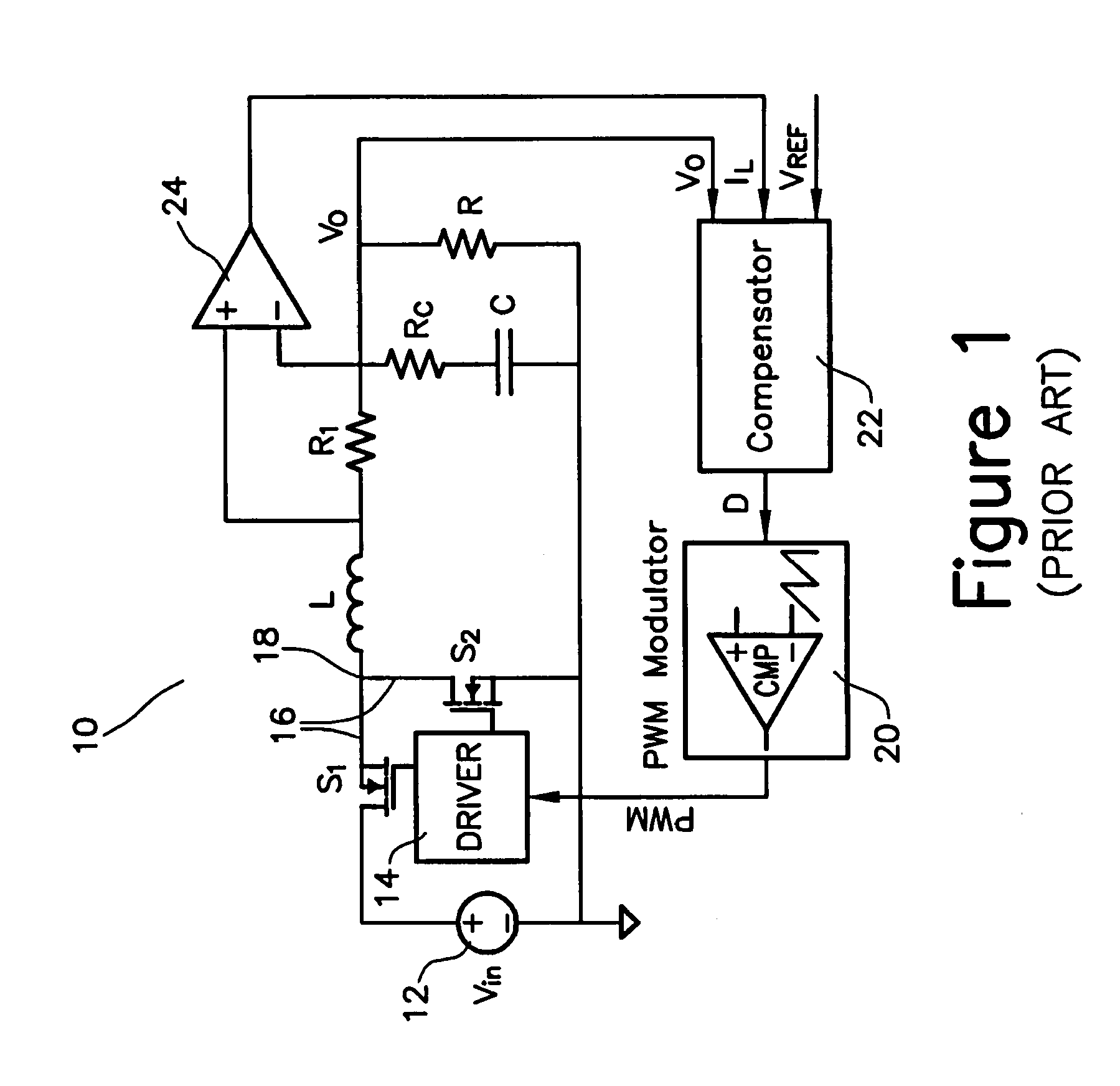
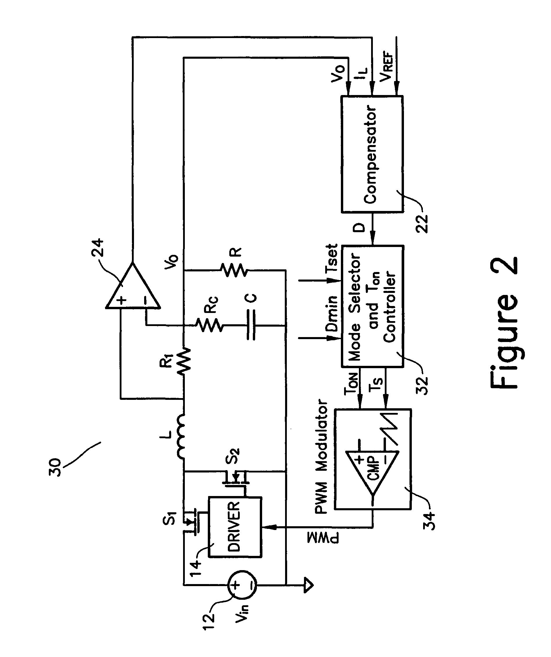
[0017]In FIG. 1 a synchronous buck converter is used for illustrative purposes. However, the same principle may be applied to other topologies, as well. In FIG. 1 circuit 10 includes a driver 14 connected to gate terminals of a half-bridge stage 16 having transistors S1 and S2 connected at a common node 18. Second terminals of the transistors S1 and S2 being connected to a source 12. The driver 14 controlling the half-bridge stage 16 in accordance with PWM signals received from a PWM modulator 20. The PWM signals are based on a computed duty cycle value D provided by a compensator 22.
[0018]A load L is connected to the common node 18 and series connected to a resistor R1. The resistor R1 is connected at a second node to a resistor RC that is series coupled to a capacitor C and to a resistor R. An amplifier 24 receives its positive input from the connection between the load L and the resistor R1 and the negative input from the second node. The compensator 22 receives a predefined refe...
PUM
 Abstract
Description
Claims
Application Information
 - R&D
- Intellectual Property
- Life Sciences
- Materials
- Tech Scout
- Unparalleled Data Quality
- Higher Quality Content
- 60% Fewer Hallucinations
Browse by: Latest US Patents, China's latest patents, Technical Efficacy Thesaurus, Application Domain, Technology Topic, Popular Technical Reports.
© 2025 PatSnap. All rights reserved.Legal|Privacy policy|Modern Slavery Act Transparency Statement|Sitemap|About US| Contact US: help@patsnap.com


