Optical fiber gain medium with modal discrimination of amplification

a gain medium and optical fiber technology, applied in the field of optical fiber, can solve the problems of reducing beam quality, multimode operation, and limiting the achievable power of pulsed fiber lasers and amplifiers, and achieve the effect of reducing the lasing threshold, precise control and adjustment of discrimination

Inactive Publication Date: 2010-07-20
ROFIN SINAR LASER
View PDF20 Cites 24 Cited by
  • Summary
  • Abstract
  • Description
  • Claims
  • Application Information

AI Technical Summary

Benefits of technology

[0013]According to further aspects of the invention said barrier layer in the fiber is either eccentrically positioned between said first core section and said second core section and / or has an unsymmetrical cross section so that said barrier layer has a variable thickness, for instance a smallest thickness at one side of the first core section and a greatest thickness at the opposite side of the first core section. This is especially practical in case when the optical fiber is coiled, i.e. is bent to have curvature, whereupon said smallest thickness and said greatest thickness are in a bending plane extending through the longitudinal centerline of the first core section. The bending radius of the coil is selected to have such a value that fundamental core mode is non-resonant in the optical fiber to incur gain discrimination between fundamental and higher order core modes. This bending together with asymmetrical configuration of the optical fiber enable very precise control and adjustment of the discrimination in the final product, i.e. weak coupling of the fundamental core mode with the cladding modes, but strong coupling between the higher order core modes and the cladding modes.
[0014]The novel fiber according to the present invention enables one to design a laser where the fundamental mode has the highest gain, and lowest threshold for lasing. This is accomplished by bending the fiber and modifying the fiber geometry in order to control the resonances and modal resonances.

Problems solved by technology

The small core area in such fibers, however, starts to limit the achievable power in both continuous wave (=CW) and pulsed fiber lasers and amplifiers.
Efforts to do that by simply increasing the core diameter in a conventional step index fiber readily leads to multimode operation and reduced beam quality.
Eventually, manufacturing reproducibility and accuracy for the index step become a limiting factor for making a single-mode step-index fiber when the core diameter is increased beyond a couple of tens of microns.
However, PCFs are known to have some drawbacks, namely, they are difficult to manufacture, they are quite sensitive to fiber bending, and also their splicing to conventional fibers is not easy without incurring losses.
On the other hand, reliable and reproducible manufacturing of fibers limit the minimum practical index step to a value of about 1×10⁻³.
Hence, manufacturing tolerances for the index step become a limiting factor for making a single-mode step-index fiber when the core diameter is increased beyond a couple of tens of microns.
The problem of these methods is the manufacturability and reproducibility of the structures.
The control of the doping profile and the location, width and refractive indices of the surrounding cladding layers is difficult.
However, for large-core fibers this requires rather small bending radius that, on the other hand, may cause the fiber to break or adversely affects its durability.
In summary, the operation of the coiled fiber amplifier / laser is limited by the manufacturing tolerances of the index step and the tight bending radius, which induces stress on the fiber.
The latter approach is limited by the requirement of tight bending radii for large core sizes, which eventually reaches the limit of mechanical reliability or fracture of the fiber.

Method used


Image

  • Optical fiber gain medium with modal discrimination of amplification
  • Optical fiber gain medium with modal discrimination of amplification
  • Optical fiber gain medium with modal discrimination of amplification

Examples


third embodiment

[0031]The third embodiment as shown in FIG. 7 is also quite similar having a doped first core section 11, a barrier layer 12, an undoped second core section 13, and a cladding 14 all with circular cross-sections, i.e. the boundaries are circular. Here the first boundary 21, the third boundary 23 and fourth boundary 24 are concentric, but the barrier layer 12 is asymmetrically positioned around to the first core section 11, whereupon the second boundary 22 is not concentric. The bending plane P that goes through the centers of the circular first, second, third and fourth boundaries is also shown. As can be seen, the thickness of the barrier layer 12 is smallest d2min at one side of the first core section 11 and greatest d2max at the other side thereof, when measured along the bending plane P. The refractive index profile of this asymmetrical optical fiber 10 when in straight state is shown in FIG. 11A, and along the bending plane P. In the disclosed asymmetrical fibers at least the b...

fourth embodiment

[0032]Further, the fourth embodiment as shown in FIG. 8 is quite similar, too, comprising a doped first core section 11, a barrier layer 12, a second core section 13, and a cladding 14, in which fiber 10, the first core section 11, the second core section and the cladding 14 have circular cross-sections, i.e. the boundaries are circular. In this case the barrier layer 12 is symmetrically located with respect to the first core section 11, the second core section 13 and the cladding 14, more specifically the circular portion of its second boundary 22, the first boundary 21, the third boundary 23 and the fourth boundary 24 are concentric, but the second boundary 22 has a flat side 221 extending in the longitudinal direction of the fiber 10, i.e. the second boundary 23 has a cut-away segment. The bending plane P that goes through the common center of the boundaries is also shown. Just like in FIG. 7 the thickness of the barrier layer is smallest d2min the at one side of the first core s...

fifth embodiment

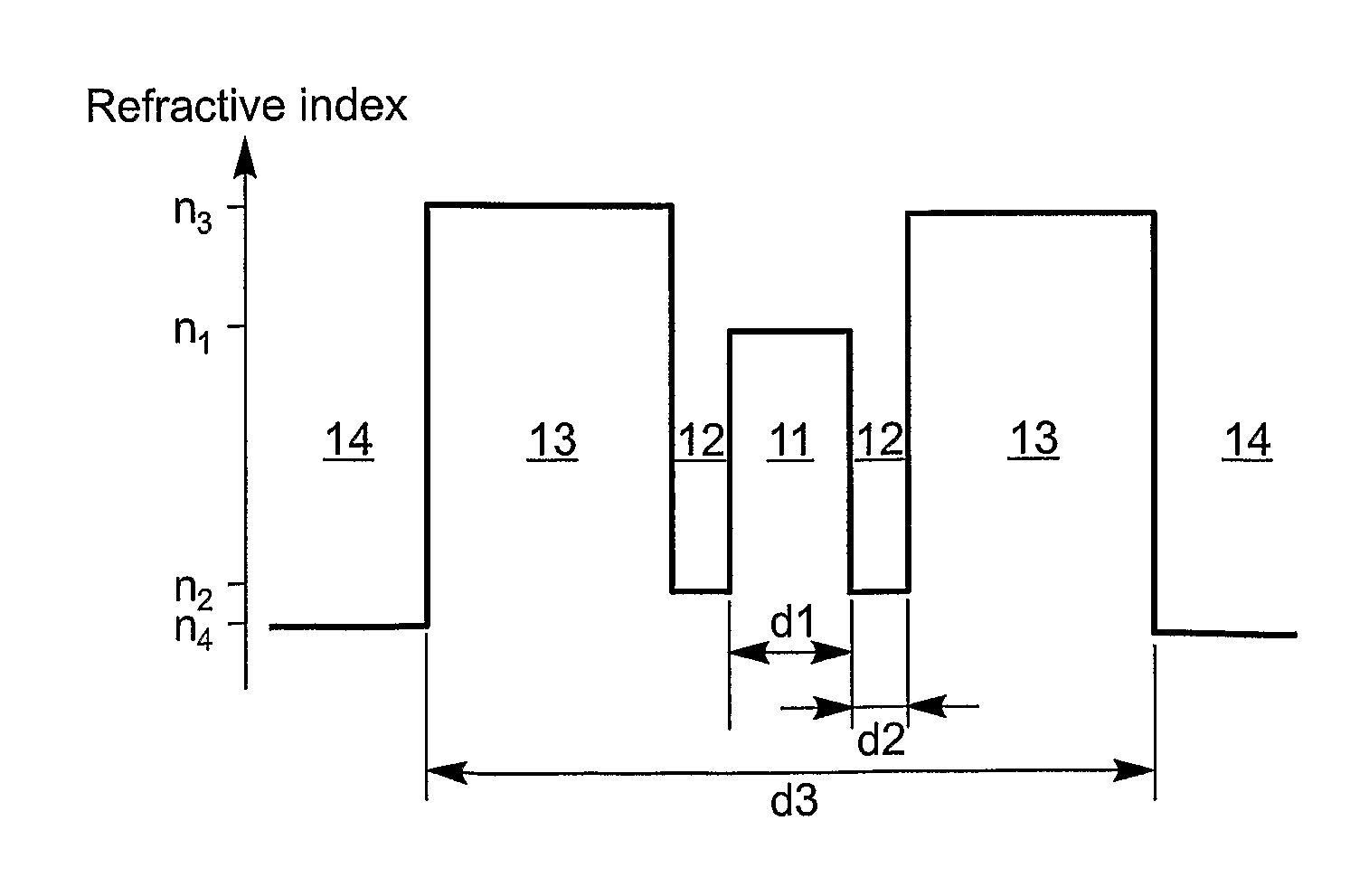
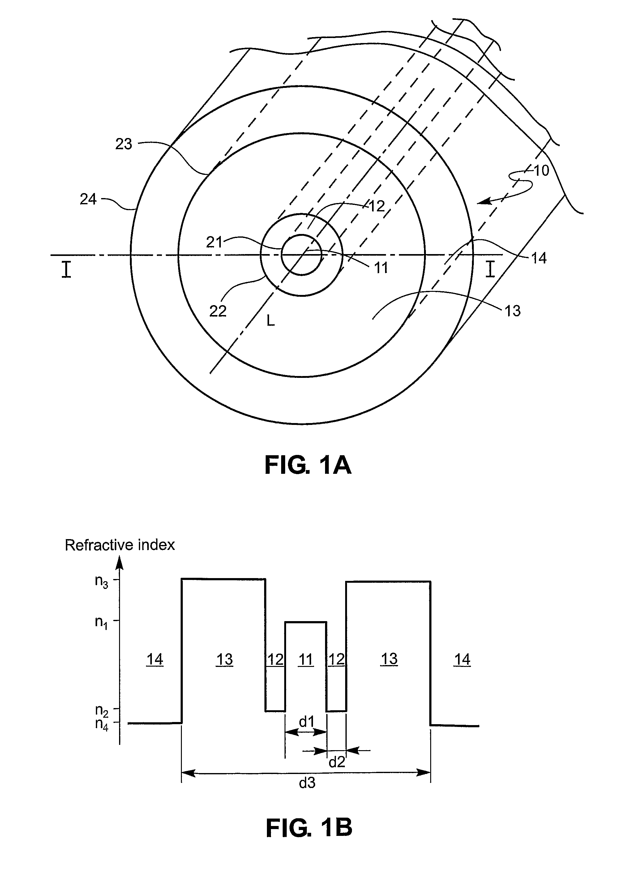
[0033]The fifth embodiment as shown in FIG. 9 deviates more from those embodiments discussed above. In this embodiment the optical fiber 10 comprises a doped first core section 11 with a first effective refractive index n1 and a circular first boundary 21, a barrier layer 12 with a second refractive index n2, and a circular second boundary 22, an undoped second core section 13 with a third effective refractive index n3, but having a rectangular third boundary 23, and a cladding 14 with a fourth refractive index n4 and a rectangular fourth boundary 24. The doping and undoping as well as the refractive indices are like in the other embodiments of the invention. In this case, the first core section 11 is centered and the barrier layer 12 is asymmetrically positioned like in embodiment of FIG. 7, and the bending plane P goes through the centers of their circular boundaries 21, 22. The bending plane P is arranged perpendicular to the longer widths W1a, W2a of the second core section and ...


PUM


Abstract

An active multimode optical fiber consisting of a first core section (11), a thin barrier layer (12) material having a thickness (d2) and a lower refractive index than that of the first core section by an index difference (Δn), a second core section (13) having a refractive index equal or higher than that of the first core section, and a cladding (14) having an index lower than that of the first core section. Said index difference and said thickness are selected so that a fundamental core mode couples less strongly with said cladding modes than higher order core modes. A scheme of changing the symmetry of the fiber for reduced sensitivity of the fundamental mode of the first core section to resonance effects.

Description

[0001]This application is the US national phase of international application PCT / FI2005 / 000342 filed 27 Jul. 2005 which designated the U.S. and claims benefit of FI 20045308, dated 26 Aug. 2004, the entire content of which is hereby incorporated by reference.FIELD OF THE INVENTION[0002]The present invention relates to an optical fiber comprising a first doped core and at least a second undoped core surrounding the first core, said first core having a first refractive index, and said second core having a third refractive index. The present invention also relates to a multimode optical fiber amplifier apparatus for providing optical gain discrimination between the desired fundamental mode and the undesired higher order modes, said amplifier apparatus comprising an active fiber comprising a doped core and at least a second undoped core surrounding the first core, said first core having a first refractive index, and said second core having a third refractive index. The present invention...

Claims


Application Information

Patent Timeline
Patent Type & Authority Patents(United States)
IPC IPC(8): H01S3/30G02B6/032G02B6/036G02BH01S3/067
CPCG02B6/03611G02B6/03644H01S3/06708
Inventor SALOKATVE, ARTOYLA-JARKKO, KALLE
Owner ROFIN SINAR LASER
Why Eureka
Try Eureka