Method and system for LASER machining
a laser machining and laser technology, applied in the field of laser machining methods and systems, can solve the problems of difficult and costly manufacturing of such small features of pore arrays, difficulty in drilling holes with exit diameters less than, and inability to meet the requirements of the application, so as to increase the number of repetitions, reduce the amount of time required, and increase the amount of power.
- Summary
- Abstract
- Description
- Claims
- Application Information
AI Technical Summary
Benefits of technology
Problems solved by technology
Method used
Image
Examples
example 1
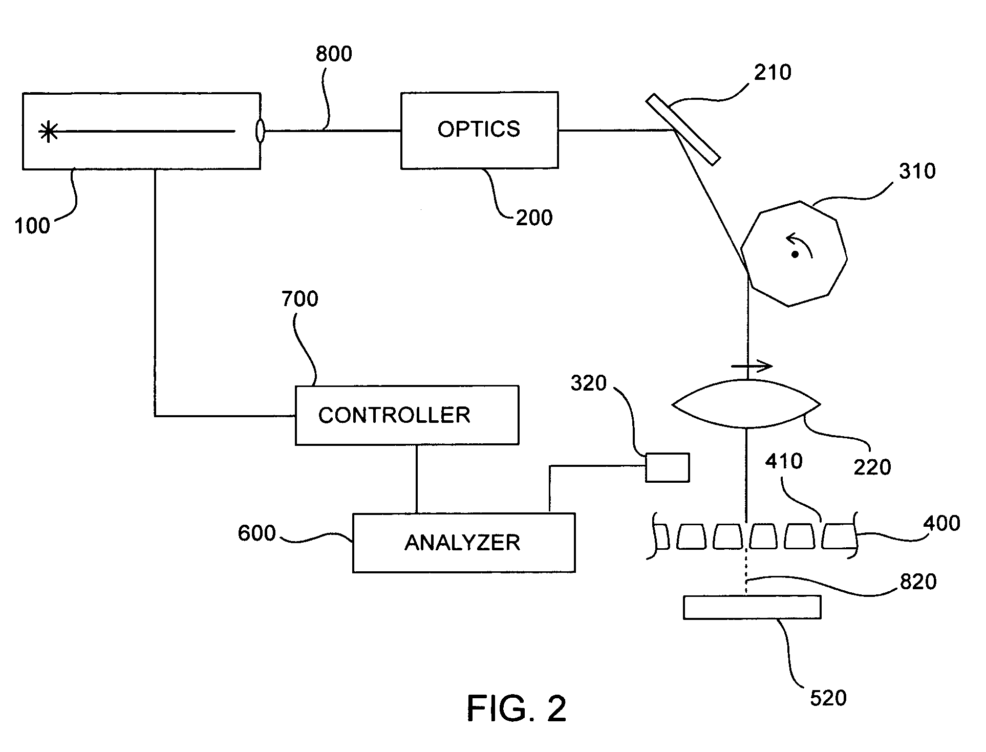
[0093]In this example, a single-hole LASER drilling process was developed based a 5 kHz LASER pulse rate, and a higher processing speed was desired. Later, a LASER with a 100 kHz pulse rate became available. Rather than increasing the pulse rate on a single feature, the beam can be scanned repeatedly across the work piece at 5 kHz or less using an oscillating mirror (340, FIGS. 4 and 5). The LASER pulses are synchronized with the oscillation of the mirror using a detector (320) with a narrow slit covering the sensitive surface, placed next to the part to be machined. As the beam scans across the slit, the LASER (100) is triggered to pulse in high-energy mode, so that high energy pulses are repeatedly directed to the same set of sequential locations (410). In this way, each of 20 or more different locations are each exposed to 5 kHz or less drilling operations using a single 100 kHz LASER. In the previously developed process, the drilling on a single hole is terminated when a certain...
example 2
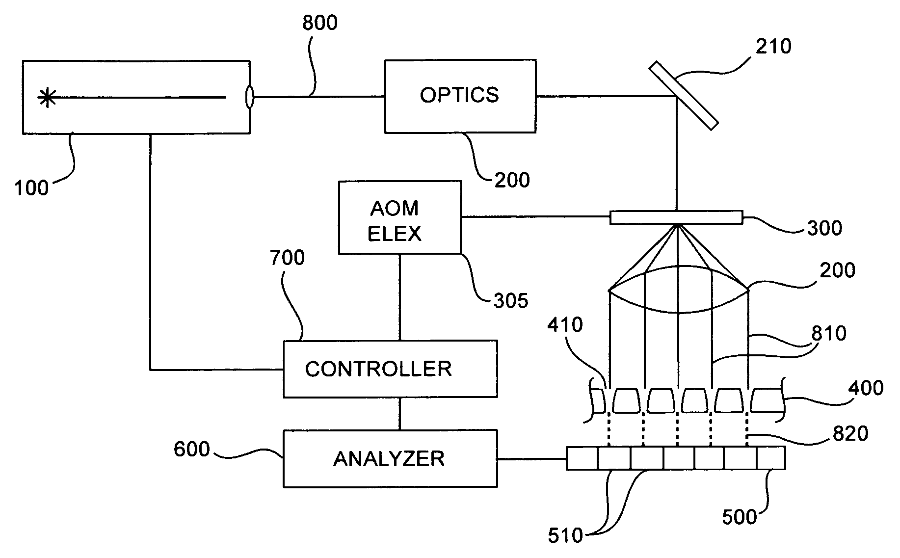
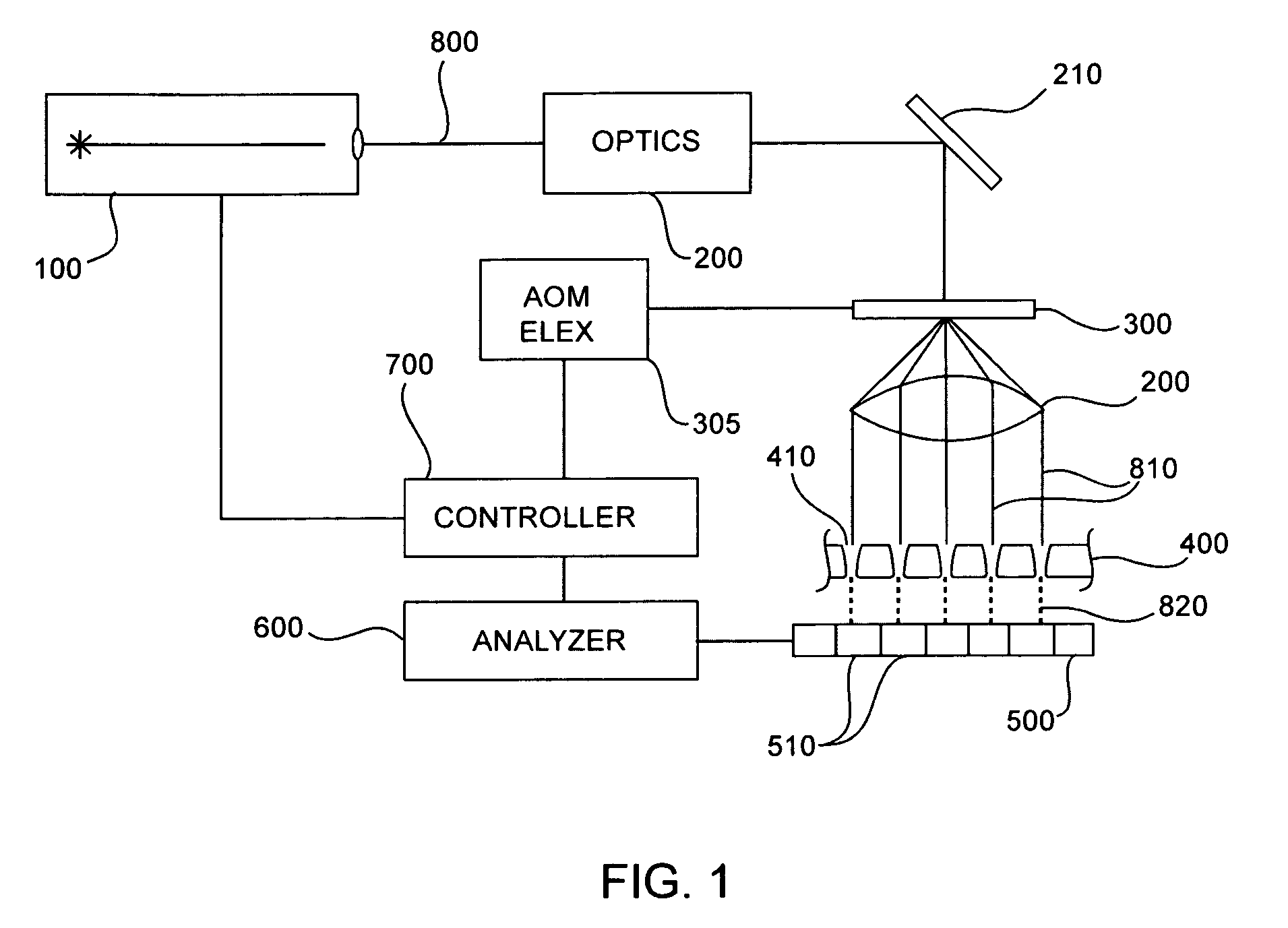
[0094]In this example, a single-hole LASER drilling process was developed based on a 5 kHz pulse repetition rate, and a higher processing speed was desired. In order to drill many holes at once, the LASER beam can be split into many beams using an acousto-optic modulator. This splitting can be in one or two dimensions, but one dimensional splitting is simpler and easier to explain and is used in this example (FIG. 1). Each beam (810) is formed by the incident LASER beam (800) interacting with a density variation in the acousto-optic element (300). The density variation results from a sound wave typically generated by driving the acousto-optic element with an electrical signal of an appropriate frequency. Thus each beam corresponds to a frequency and the beam intensity can be adjusted by adjusting the amplitude of the electrical signal at that frequency. All of the signals are combined electrically and applied to the acousto-optic element to generate all of the beams at once. In the ...
example 3
[0095]In this example, 10 holes are drilled at once using a laser pulsing at 100 kHz and directing each pulse sequentially at the 10 holes consecutively. The system described above can be used, but with the synthesizer driving the AOD reprogrammed to multiplex the pulses to the 10 holes in time, using the same pre-programmed sequence for each one. The synthesizer then synchronizes with the laser pulsing and the detector response, tracking which of the 10 holes has been processed to completion and skipping those holes. In either case, the synthesizer returns control to the next level controller in the system once it has completed drilling the 10 holes.
PUM
| Property | Measurement | Unit |
|---|---|---|
| diameter | aaaaa | aaaaa |
| diameter | aaaaa | aaaaa |
| diameter | aaaaa | aaaaa |
Abstract
Description
Claims
Application Information
 - R&D
- Intellectual Property
- Life Sciences
- Materials
- Tech Scout
- Unparalleled Data Quality
- Higher Quality Content
- 60% Fewer Hallucinations
Browse by: Latest US Patents, China's latest patents, Technical Efficacy Thesaurus, Application Domain, Technology Topic, Popular Technical Reports.
© 2025 PatSnap. All rights reserved.Legal|Privacy policy|Modern Slavery Act Transparency Statement|Sitemap|About US| Contact US: help@patsnap.com


