Solid electrolytic capacitor and method for producing the same

a solid electrolytic capacitor and electrolytic technology, applied in capacitors, hybrid capacitor electrolytes, capacitors, etc., can solve the problems of difficult to further reduce esr in, particularly in the high frequency range, and achieve the effects of reducing contact resistance, improving adhesion, and reducing esr

Active Publication Date: 2010-09-21
SANYO ELECTRIC CO LTD
View PDF13 Cites 35 Cited by
  • Summary
  • Abstract
  • Description
  • Claims
  • Application Information

AI Technical Summary

Benefits of technology

[0025]In the present invention, the intermediate layer containing organic silane is formed between the first and second electrolyte layers containing a conductive polymer, thereby improving adhesion between the first and second electrolyte layers. This reduces contact resistance between the first and second electrolyte layers, making it possible to reduce ESR in a high frequency range. As a result, a solid electrolytic capacitor having a small ESR can be obtained.
[0026]As the organic silane contained in the intermediate layer, a methyl type, phenyl type, vinyl type, alkoxy type, mercapto type or amino type silane may be used. Particularly, the amount of ESR can be easily reduced by using at least one organic silane selected from the group consisting of APTES, OTES, nPTCS, DMDPS, MPDCS and MPTMS.
[0027]Also, ESR can be further reduced by using PEDOT having high conductivity to form the first electrolyte layer and by using a highly conductive PPy produced by electrolytic polymerization to form the second electrolyte layer.
[0028]Also, after the first electrolyte layer is formed, an organic silane solution is applied and dried, whereby an intermediate layer containing the organic silane can be easily formed on the first electrolyte layer. Also, adhesion between the first and second electrolyte layers can be easily improved by forming the second electrolyte layer on the intermediate layer.
[0029]Also, adhesion between the dielectric layer and the first electrolyte layer can be improved by forming the first electrolyte layer by chemical polymerization. Also, a highly conductive second electrolyte layer can be formed by forming the second electrolyte layer by electrolytic polymerization.

Problems solved by technology

However, in the foregoing conventional solid electrolytic capacitor, contact resistance between the first electrolyte layer 106a and the second electrolyte layer 106c tends to be large, giving rise to a problem that it is difficult to further decrease ESR in, particularly, a high frequency range.

Method used


Image

  • Solid electrolytic capacitor and method for producing the same
  • Solid electrolytic capacitor and method for producing the same
  • Solid electrolytic capacitor and method for producing the same

Examples


first embodiment

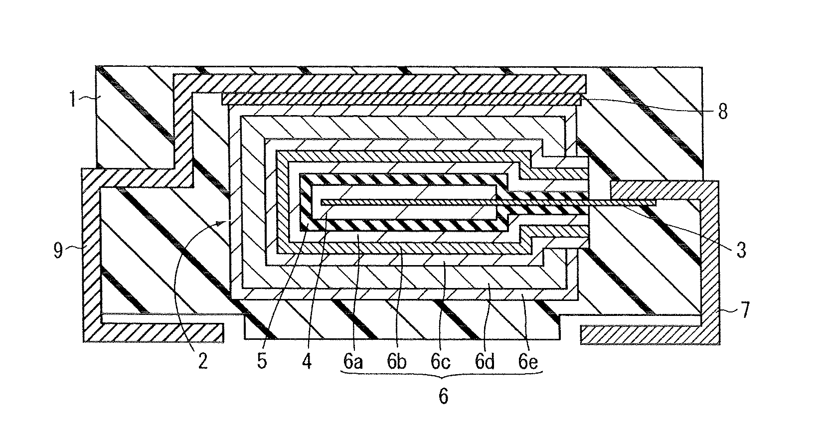
[0040]FIG. 1 is a sectional view for explaining the structure of a solid electrolytic capacitor according to a first embodiment of the present invention. The structure of the solid electrolytic capacitor according to the first embodiment of the present invention will be explained with reference to FIG. 1.

[0041]In the solid electrolytic capacitor according the first embodiment of the present invention, a capacitor element 2 is buried in an outer package 1 having a rectangular parallelepiped-like form and primarily made of an epoxy resin as shown in FIG. 1.

[0042]The capacitor element 2 is provided with an anode 4 in which a part of an anode lead 3 is buried and which is constituted of a porous sintered body of a valve metal such as tantalum or niobium, a dielectric layer 5 which is formed on the anode 4 and contains an oxide of the above valve metal and a cathode 6 formed on the dielectric layer 5.

[0043]One end of the anode lead 3 is buried in the center of the anode 4, and one end of...

experiment 1

[0061]In Experiment 1, solid electrolytic capacitors A1 to A5 having the structures shown in Table 1 were manufactured.

[0062]Here, the anode 4 was formed from a porous sintered body of tantalum or niobium particles. For the anode lead 3, a metal line made from tantalum was used.

[0063]Also, each anode 4 was dipped in an aqueous solution containing about 0.1 wt % of phosphoric acid which was kept at about 60° C. and a fixed voltage of about 8 V was applied to the anode 4 for about 10 hours to from the dielectric layer 5 made of a tantalum oxide or niobium oxide.

[0064]Also, the first electrolyte layer 6a was formed by chemical polymerization in the following manner. First, the anode 4 provided with the dielectric layer 5 on its outermost surface was dipped in a solution containing about 10 wt % of EDOT or Py, about 30 wt % of p-toluenesulfonic acid, about 40 wt % of n-butanol and about 20 wt % of pure water for 10 minutes. Next, the anode 4 was taken out of this solution and heated at ...

experiment 2

[0071]In Experiment 2, solid electrolytic capacitors B1 to B5 each having the same structure as the solid electrolytic capacitor A1 were produced except that as the intermediate layer 6b, octadecyltriethoxysilane (OTES), n-propyltrichlorosilane (nPTCS), dimethoxydiphenylsilane (DMDPS), methylphenyldichlorosilane (MPDCS) or mercaptopropyltrimethoxysilane (MPTMS) was used in place of APTES.

[0072]Each intermediate layer 6b of the solid electrolytic capacitors B1 to B5 was formed in the same manner as in the process of manufacturing the solid electrolytic capacitor A1 except that the first electrolytic layer 6a was dipped in an aqueous solution containing about 0.002 wt % of each of OTES, nPTCS, DMDPS, MPDCS and MPTMS instead of dipping the first electrolyte layer 6a in the aqueous solution containing about 0.002 wt % of APTES.

[0073]Then, the produced solid electrolytic capacitors B1 to B5 were subjected to ESR measurement made at a frequency of about 100 kHz. The ESR measurement was ma...


PUM

PropertyMeasurementUnit
fixed voltageaaaaaaaaaa
current flowaaaaaaaaaa
frequencyaaaaaaaaaa

Abstract

A solid electrolytic capacitor, having a small equivalent series resistance, is formed by burying a capacitor element inside an epoxy resin outer package. The capacitor element includes an anode, having part of an anode lead buried therein, a dielectric layer formed on the anode and containing a niobium oxide, and a cathode formed on the dielectric layer. The cathode includes a first electrolyte layer containing a conductive polymer and formed on the dielectric layer, an intermediate layer containing an organic silane and formed on the first electrolyte layer, a second electrolyte layer containing a conductive polymer and formed on the intermediate layer, a first conductive layer containing carbon particles and formed on the second electrolyte layer, and a second conductive layer containing silver particles and formed on the first conductive layer.

Description

BACKGROUND OF THE INVENTION[0001]1. Field of the Invention[0002]The present invention relates to a solid electrolytic capacitor and a method for producing the same.[0003]2. Description of the Related Art[0004]Conventionally, solid electrolytic capacitors having a small equivalent series resistance (ESR) have been known (see, for example, Japanese Unexamined Patent Publication Nos. 4-48710, 10-92699 and 10-321471).[0005]FIG. 9 is a sectional view for explaining the structure of a conventional solid electrolytic capacitor. The structure of this conventional solid electrolytic capacitor will be explained with reference to FIG. 9.[0006]In the conventional solid electrolytic capacitor, as shown in FIG. 9, a capacitor element 102 is buried in a rectangular parallelepiped-like outer package 101.[0007]The capacitor element 102 is provided with an anode 104 in which a part of an anode lead 103 is buried and which is made of a porous sintered body of tantalum particles, a dielectric layer 105...

Claims


Application Information

Patent Timeline
Patent Type & Authority Patents(United States)
IPC IPC(8): H01G9/02H01G9/00
CPCH01G9/025H01G11/56H01G11/48Y10T29/417Y02E60/13
Inventor IIDA, TAKAHISAYANO, MUTSUMIUMEMOTO, TAKASHINONOUE, HIROSHI
Owner SANYO ELECTRIC CO LTD
Why Eureka
Try Eureka