
Blood vessel occlusion auger

a technology auger, which is applied in the field of blood vessel occlusion auger, can solve the problems of high morbidity and death risk, slow blood flow, and the inability of a guide wire to navigate through and distally past the occlusion, so as to reduce the spring rate coefficient of deflection, prevent the passage of the force applicator, and improve the effect of reducing the dimension

Inactive Publication Date: 2010-09-28
OVALUM LTD
View PDF29 Cites 13 Cited by
  • Summary
  • Abstract
  • Description
  • Claims
  • Application Information

AI Technical Summary

Benefits of technology

"The present invention relates to a device for opening a blood vessel that is partially or fully occluded. The device includes an auger tool that can be used in a minimally invasive surgical procedure to dilate the blood vessel. The auger tool has a flexible and resilient bow that can be controlled to open the blood vessel. The device also includes a force applicator that can be used to deflect the bow and a control system to manage the device. The invention provides an improved method for opening a blood vessel that is partially or fully occluded, which involves using an occlusion auger to dilate the blood vessel and restore blood flow."

Problems solved by technology

Partial occlusion of any artery or vein of the body, herein a vessel, may slow blood flow to the extent that affected tissue may receive inadequate perfusion of life-giving oxygen, with sequelae of tissue ischemia, ischemic pain and tissue necrosis.
In totally occluded blood vessels, including Chronic Total Occlusions (CTO's), the size of the occlusion and its hardness often make it impossible for a guide wire to navigate through and distally past the occlusion.
Restoring blood flow through a totally occluded vessel often requires opening the chest and installing vessels that bypass the occlusion, a surgical procedure associated with high morbidity and risk of death.

Method used


Image

  • Blood vessel occlusion auger
  • Blood vessel occlusion auger
  • Blood vessel occlusion auger

Examples


embodiment 1000

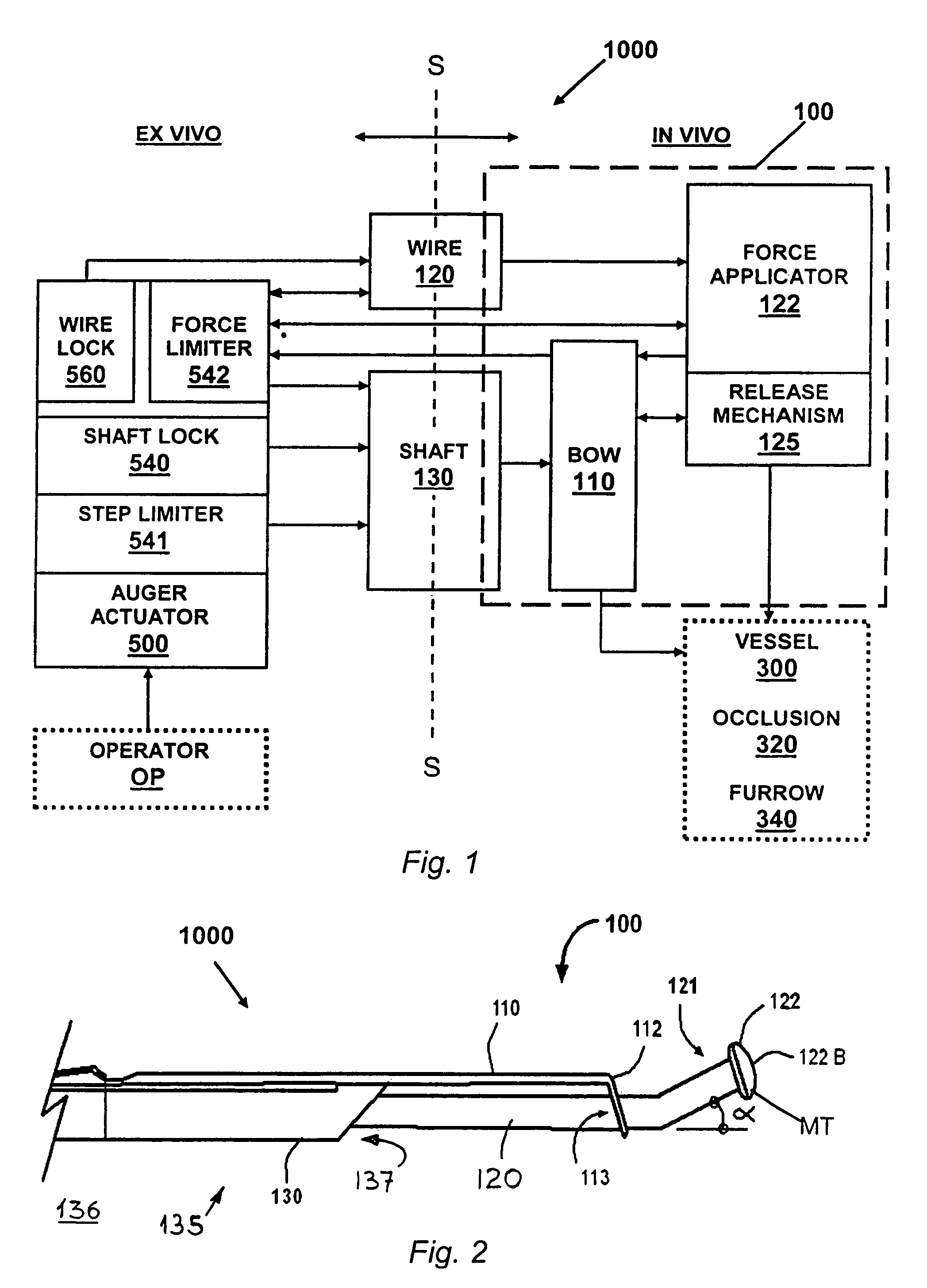
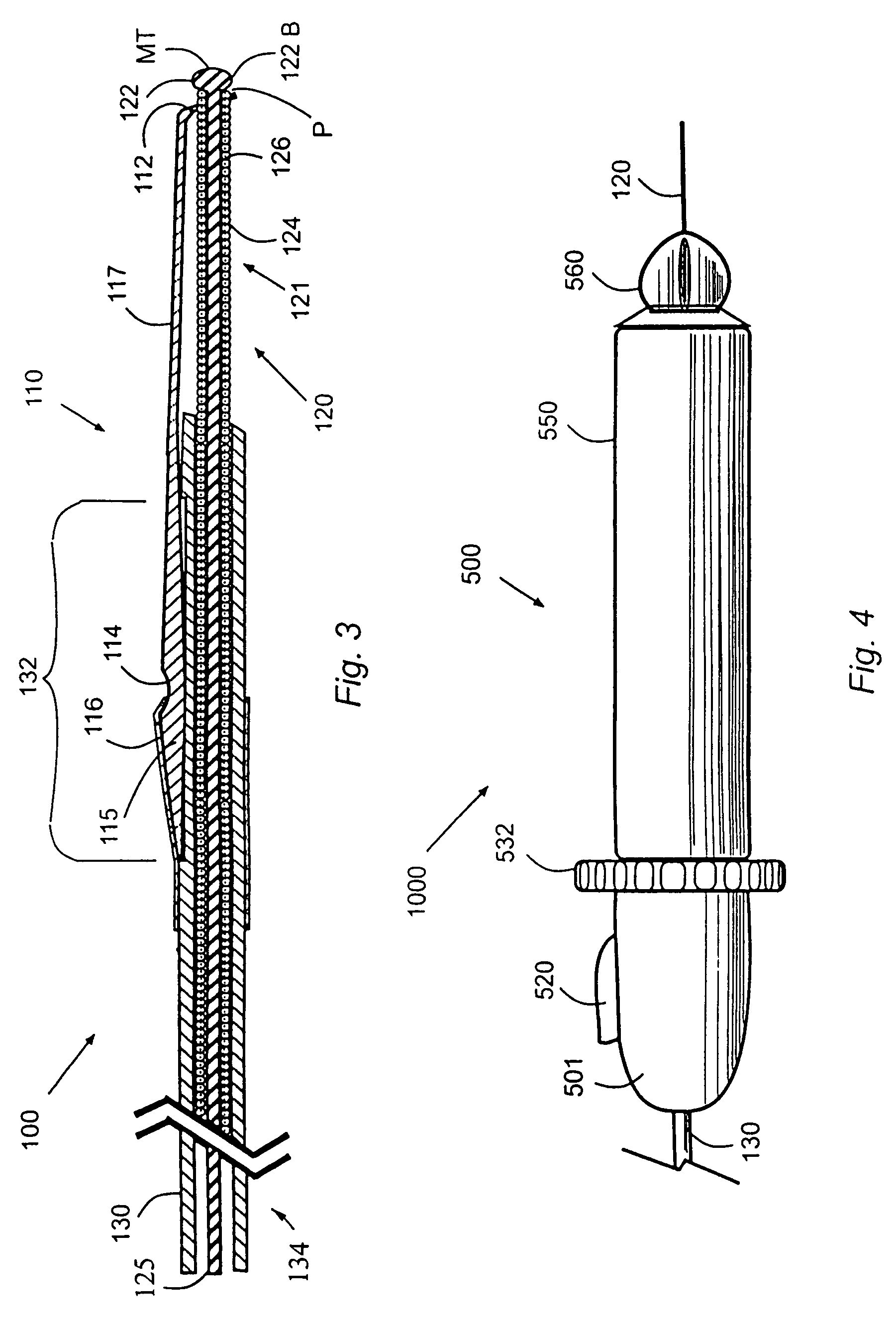
[0078]An operator OP handles the occlusion auger 1000 via an ex vivo auger actuator 500, which controls an in vivo auger tool 100 operating a distal portion of the wire 120 and of the shaft 130. In the preferred embodiment 1000, the auger tool 100 has for example, a flexible and resilient element, such as a bow 110, fixedly coupled to the distal portion of the shaft 130, and removably engaging an in vivo force applicator 122 fixed to the in vivo distal extremity of the wire 120.

[0079]In operation, the wire 120 is first navigated distally via blood vessels 300, inside vessel walls 310, until the force applicator 122 engages an occlusion 320, or a furrow 340 in an occlusion 320. Then, the shaft 130 and the force applicator 122 are coupled and operated to flex and arcuate the bow 110. Thereby, the force applicator 122 and the extrados of the arcuate flexed bow back 117 are embeded in occlusion tissue lining the furrow 340, in releasable anchoring disposed adjacent opposite vessel walls...

embodiment 200

[0181]FIGS. 23A to 23C illustrate a distal portion of the auger tool, as embodiment 200, with a different type of force applicator 122 and face 112, and with reduced dimensions. In FIGS. 23A to 23C reference is made to the planar face 112, but the same applies to the twisted face 112T, with and without one or more cutting-edge(s) 112C.

[0182]As shown in FIG. 23A, the force applicator 122 is configured as a limited length of male screwthread 122M disposed at the distal extremity of the wire 120, instead of the bulb 122B shown in FIGS. 2 and 3. The face 112, shown in FIG. 23B, operates as a female screwthread 113F, or may be fitted therewith, in replacement of the cylindrical face bore 113, to receive the male screwthread 122M therein in matching and in extension therethrough.

[0183]To extend the male screwthread 122M distally outward of the face 112, as shown in FIG. 23C, the male screwthread 122M is rotated and threadingly engaged until distally emerging thereout. Thereafter, once dis...


PUM


Abstract

A blood occlusion auger having an in vivo distal auger tool coupled in operative association with an ex vivo auger control for opening and traversing occlusions in a blood vessel The auger control allows the selection of predetermined threshold forces and step-lengths values and operates in successive repetition of identical sequential stages, to traverse occlusions. Once disposed adjacent an occlusion, the auger tool, commanded by the auger control, operates in two states, first to radially dilate the vessel and second to penetrate distally into a furrow.

Description

[0001]This application is a Continuation of PCT / IL2005 / 000607 filed Jun. 8, 2005, the priority date of which is claimed herein, and the entire disclosure of which is incorporated herein by reference.Technical Field[0002]The present invention relates to devices and methods for restoring blood flow in occluded blood vessels, and for traversing occlusions.Definitions[0003]Distal refers to both a direction of motion and a location, respectively, a movement in a direction away from an operator or a location further from the operator, for example a portion of an instrument located in vivo.[0004]Proximal refers to both a direction of motion and a location, respectively, a movement in a direction toward the operator or a location nearer to the operator, for example a portion of an instrument located ex vivo.[0005]Axial indicates the direction substantially in the longitudinal axis of a blood vessel.[0006]Lateral and radial refer to a direction substantially perpendicular to the longitudinal...

Claims


Application Information

Patent Timeline
Patent Type & Authority Patents(United States)
IPC IPC(8): A61B17/22A61MA61M39/00
CPCA61B17/3207A61B17/221A61B17/320725A61B2017/320733A61B2017/22042A61B2017/22094A61B2017/00469
Inventor SHAMAY, NOAM
Owner OVALUM LTD
Learn More