Metal-clad laminate and method for production thereof

a metal-clad laminate and metal-clad technology, applied in the field of metal-clad laminate, can solve the problems of difficult continuous and stable production, difficult to provide excellent isotropy and dimensional stability of metal-clad laminate, etc., and achieve improve the dimensional stability of thermoplastic liquid crystal polymer film, excellent isotropy and dimensional stability

Active Publication Date: 2010-10-12
KURARAY CO LTD
View PDF9 Cites 3 Cited by
  • Summary
  • Abstract
  • Description
  • Claims
  • Application Information

AI Technical Summary

Benefits of technology

[0007]An object of the present invention is to provide a metal-clad laminate, and a method for production thereof, which is effective to provide a metal-clad laminate excellent in isotropy, appearance, adhesive force between the polymer film and the metallic sheet, and dimensional stability with high productivity by the use of a continuous manufacturing technique using the heating rolls.
[0009]As hereinabove described, when the stretched thermoplastic liquid crystal polymer film and the metallic sheet are thermally compressed to bond them together as they are passed through the nipping region between the heating rolls, anisotropy in the longitudinal thermal expansion is developed in the thermoplastic liquid crystal polymer film by the effect of the tension acting on those materials in the longitudinal direction of the film, and the pressure imposed on the film in the longitudinal direction thereof by the heating rolls. According to the present invention, by the use of the thermoplastic liquid crystal polymer film having the thermal expansion coefficients αL and αT of the film in the lengthwise (longitudinal) direction and the widthwise (transverse) direction falling within the specified ranges, respectively, during the first step when the thermoplastic liquid crystal polymer film and the metallic sheet are thermally compressed as they pass through the nipping region between the heating rolls while a tension is applied continuously to the film in the longitudinal direction thereof, such anisotropy can be counterbalanced by the molecular orientation of the thermoplastic liquid crystal polymer film, tending to orient the molecules in a direction transverse to the longitudinal direction of the film, thereby eliminating the anisotropy of the thermal expansion coefficient of the thermoplastic liquid crystal polymer film. As a result, the metal-clad laminate excellent in isotropy and appearance can be obtained stably. Also, when a heat treatment is performed on the resultant metal-clad laminate under a specific temperature condition, the strong bondability between the polymer film and the metallic sheet is achieved to provide the metal-clad laminate excellent in dimensional stability having a desired rate of dimensional change. In this way, the metal-clad laminate excellent in isotropy, appearance, bondability between the polymer film and the metallic sheet, and dimensional stability can be obtained with a high productivity resulting from the continuous manufacture with the use of the heating rolls.
[0022]The thermoplastic liquid crystal polymer film used in the present invention can be obtained by extrusion-molding of the above-mentioned thermoplastic liquid crystal polymer. At this time, although any extrusion molding methods can be employed, industrially advantageous one includes T-die film forming and stretching method, laminate stretching method, inflation method and the like. Particularly with the inflation method, stresses can be applied not only in a direction of the mechanical axis of the film (the longitudinal direction of the film referred to above) (which direction is hereinafter referred to as “MD direction”), but also in a direction perpendicular to the MD direction (the transverse direction of the film referred to above) (which direction is hereinafter referred to as “TD direction”) and, therefore, it possible to obtain the film, of which mechanical properties and thermal characteristics in both of the MD direction and the TD direction are well counterbalanced with each other.
[0023]The thermoplastic liquid crystal polymer film referred to above is required to have a coefficient αL (×10−6 cm / cm / ° C.) of thermal expansion in the longitudinal direction of the film, which coefficient in relation to a thickness T (μm), a thickness coefficient β (×1 / (μm×° C.)) and an anisotropy coefficient γ (×10−6 cm / cm / ° C.) of the film, satisfies the equation, αL=βT+γ. At the same time, the thickness coefficient β, the anisotropy coefficient γ relative to a thermal expansion coefficient (αM) of the metallic sheet and a coefficient αT of thermal expansion of the film in the transverse direction relative to the thermal expansion coefficient αM of the metallic sheet must be within the range of −0.08 to −0.01, i.e., (−0.08≦β≦−0.01), the range of +6 to +10 (×10−6 cm / cm / ° C.), i.e., (αM+6≦γ≦αM+10), and the range of −2 to +3 (×10−6 cm / cm / ° C.), i.e., αM−2≦αT≦αM+3), respectively. The required thermal expansion coefficient of the thermoplastic liquid crystal polymer film may vary, depending on fields of application, within the specific range discussed above. The thermoplastic liquid crystal polymer film having the thermal expansion coefficient within this specific range has a mechanical property and a thermal characteristic in both of the MD and TD directions, which are not balanced with each other. The thermoplastic liquid crystal polymer film, however, does not pose any practical problem and is, as will be discussed later, advantageous in improvement in isotropy, appearance, bondability between the polymer film and the metallic sheet, and dimensional stability when such film is eventually used to form the metal-clad laminate.

Problems solved by technology

In addition, with the techniques disclosed in each of those prior art patent documents, it is difficult to obtain continuously and in a stabilized fashion, the metal-clad laminate excellent in isotropy and dimensional stability.
As a result thereof, it is difficult to provide the metal-clad laminate excellent in isotropy and dimensional stability.

Method used


Image

  • Metal-clad laminate and method for production thereof
  • Metal-clad laminate and method for production thereof
  • Metal-clad laminate and method for production thereof

Examples


reference example 1

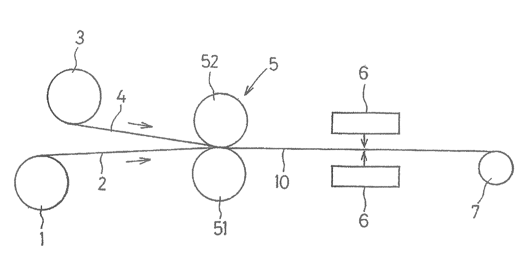
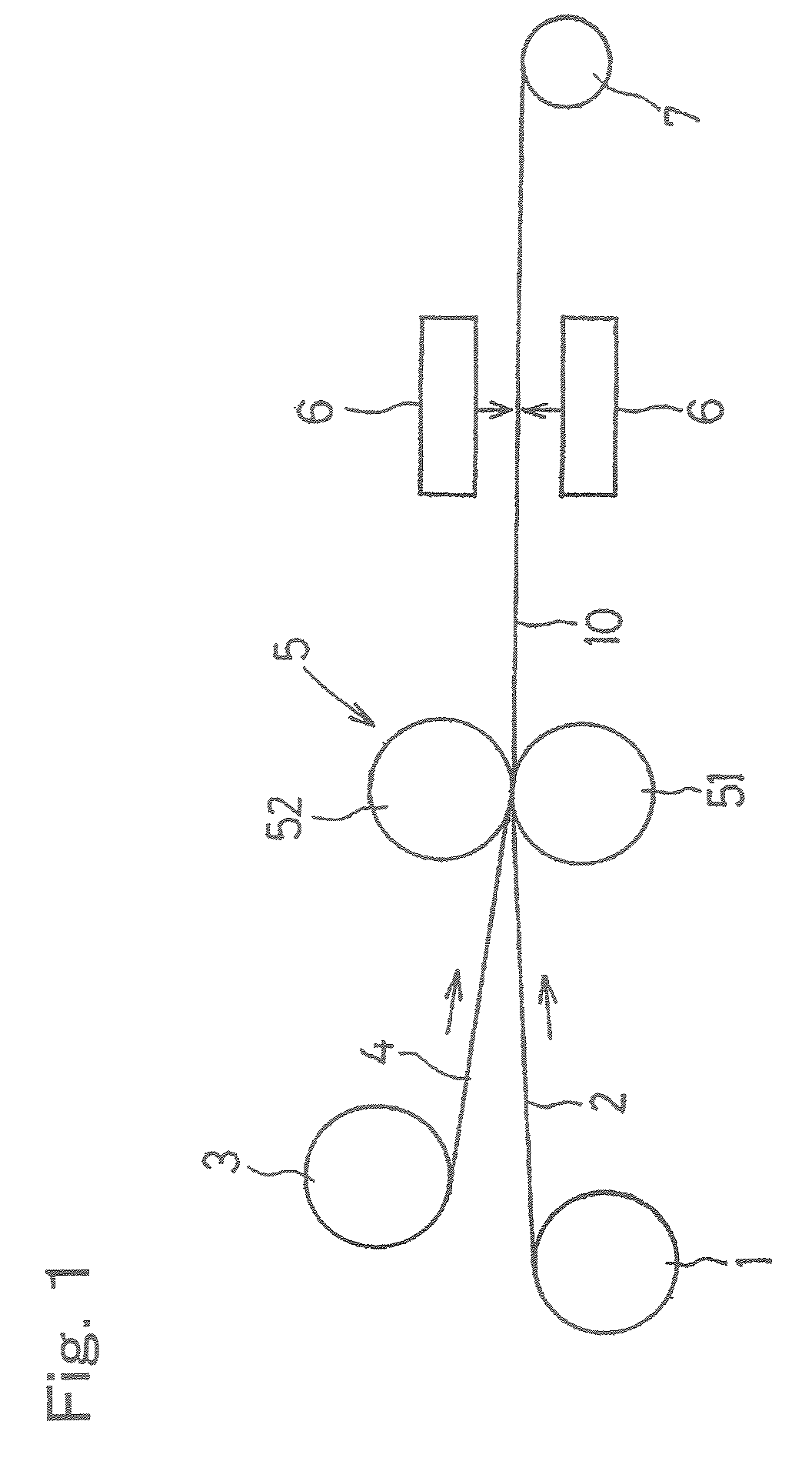
[0045]A thermoplastic liquid crystal polymer, which was a copolymer of p-hydroxy benzoic acid and 6-hydroxy-2-naphthoic acid and had a melting point of 280° C. was melt-extruded and was then formed into films, having respective film thicknesses of 25, 50, 100 and 225 μm, by an inflation molding method under a condition in which the ratio of drawing in longitudinal and transverse directions was controlled. Each of those resultant films, after having been overlapped with a respective aluminum foil which had a film thickness of 30 μm and was applied thereon with a mold releasing agent, was thermally compressed to bond to the metallic foil by passing them through a nipping region between a metallic heating roll of 260° C. and a heat resistant rubber roll under a pressure of 20 kg / cm2, and was subsequently heat treated for 30 seconds in a heating furnace, which had been heated to a temperature required for the coefficient of thermal expansion αL of each of those films having the differen...

reference example 2

[0047]A thermoplastic liquid crystal polymer, which was a copolymer of p-hydroxy benzoic acid and 6-hydroxy-2-naphthoic acid and had a melting point of 280° C. was melt-extruded and was then formed into films, having respective film thicknesses of 25, 50, 100 and 225 μm, by an inflation molding method under a condition, in which the ratio of drawing in longitudinal and transverse directions was controlled. Each of those resultant films, after having been overlapped with a respective aluminum foil which had a film thickness of 30 μm and was applied thereon with a mold releasing agent, was thermally compressed to bond to the aluminum foil by passing them through a nipping region between a metallic heating roll of 260° C. and a heat resistant rubber roll under a pressure of 20 kg / cm2, and was subsequently heat treated for 30 seconds in a heating furnace, which had been heated to a temperature required for the coefficient of thermal expansion αL of each of those films of the different f...

reference example 3

[0049]A thermoplastic liquid crystal polymer, which was a copolymer of p-hydroxy benzoic acid and 6-hydroxy-2-naphthoic acid and had a melting point of 280° C. was melt-extruded and was then formed into films, having respective film thicknesses of 25, 50, 100 and 225 μm, by an inflation molding method under a condition, in which the ratio of drawing in longitudinal and transverse directions was controlled. Each of those resultant films, after having been overlapped with a respective aluminum foil which had a film thickness of 30 μm and was applied thereon with a mold releasing agent, was thermally compressed to bond to the aluminum foil by passing them through a nipping region between a metallic heating roll of 260° C. and a heat resistant rubber roll under a pressure of 20 kg / cm2, and was subsequently heat treated for 30 seconds in a heating furnace, which had been heated to a temperature required for the coefficient of thermal expansion αL of each of those films of the different f...


PUM

PropertyMeasurementUnit
temperatureaaaaaaaaaa
melting pointaaaaaaaaaa
temperatureaaaaaaaaaa

Abstract

A metal-clad laminate excellent in isotropy, appearance, bondability between a TLC polymer film and a metallic sheet, and dimensional stability is provided less costly with a first step of thermally compressing the film with the metallic sheet by passing them through a nipping region between heating rolls, and a second step of heat-treating the resultant metal-clad laminate at a temperature not higher than the melting point of the film, wherein the film has thermal expansion coefficient αL satisfying αL=βT+γ with thickness T, thickness coefficient β and anisotropy coefficient γ of the film; wherein the coefficient β is within the range of −0.08 to −0.01; the coefficient γ is within the range of αM+6≦γ≦αM+10 with thermal expansion coefficient αM of the metallic sheet; and thermal expansion coefficient αT of the film is within αM−2≦αT≦αM+3 with the coefficient αM.

Description

FIELD OF THE INVENTION[0001]The present invention relates to a metal-clad laminate having a film (which film is hereinafter referred to as a thermoplastic liquid crystal polymer film) including a thermoplastic polymer capable of forming an optically anisotropic melt phase (which thermoplastic polymer is hereinafter referred to as a thermoplastic liquid crystal polymer), and a method for producing such metal-clad laminate. More specifically, the metal laminate obtained in accordance with the present invention has not only excellent properties such as low moisture absorbability, heat resistance, chemical resistance and electrical properties deriving from the thermoplastic liquid crystal polymer film, but also excellent dimensional stability and is useful as materials for a flexible electric wiring board and for a circuit board on which semiconductor devices is mounted.BACKGROUND ART[0002]In recent years, demands for scale reduction and weight reduction of portable electronic devices s...

Claims


Application Information

Patent Timeline
Patent Type & Authority Patents(United States)
IPC IPC(8): B32B37/00B29C65/00
CPCB29C66/83221B29C66/83413B29C66/91935B32B15/08B32B37/20H05K1/0313H05K3/0011B29C66/91645B29C66/9141B29C66/91421B29C66/91931B29C66/91933B29C65/18Y10T428/1086B29C66/73111B29C66/7352B29C66/742B29C66/919B29K2101/12B29K2105/0079B29K2305/00B29L2009/003B29L2031/3425B32B38/0036B32B2305/55B32B2307/734B32B2311/00H05K3/022H05K2201/0141H05K2201/068H05K2203/1105B29C66/034B29C65/02B29C66/1122B29C66/45C09K2323/06Y10T428/31678B29C65/44H05K3/00
Inventor ONODERA, MINORUYOSHIKAWA, TADAO
Owner KURARAY CO LTD
Why Eureka
Try Eureka