Flat magnetic element and power IC package using the same

a magnetic element and power ic technology, applied in the direction of magnetic bodies, semiconductor/solid-state device details, magnetic paints, etc., can solve the problems of reducing the height affecting the realization of the low-loss and high-inductance device, and reducing the realization of the high-inductance device. achieve the effect of improving the magnetic permeability to the magnetic field, reducing the height, and improving the inductan

Active Publication Date: 2010-10-26
KK TOSHIBA +1
View PDF18 Cites 12 Cited by
  • Summary
  • Abstract
  • Description
  • Claims
  • Application Information

AI Technical Summary

Benefits of technology

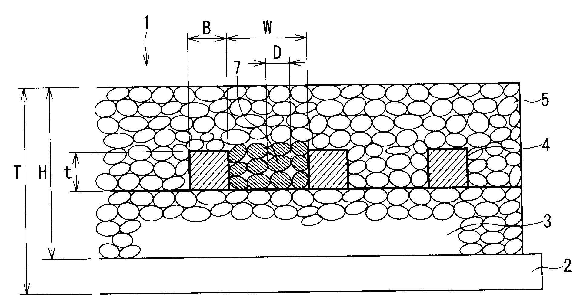
[0011]In view of the conventional circumstances that it has been difficult to obtain a high inductance device that is reduced in height as described above, an object of the present invention is to realize a planar magnetic device such as a reduced height inductor by using fine particles that enables to effectively achieve a large inductance value in a planar coil.
[0012]In order to achieve the object, the inventors have conducted an extensive research on a shape and arrangement of magnetic particles that enable to effectively obtain a large inductance value in combination with a planar coil and confirmed influences that these factors exert on magnetic device characteristics by experiments. As a result, the inventors have found that magnetic permeability to a magnetic field generated on the coil is effectively improved only when a thin film inductor is formed by filling a magnetic paste containing magnetic particles having a length ratio (shape ratio) between a long axis and a short axis within a predetermined range between planar coils, and that a reduced height inductor with improved inductance value is realized.

Problems solved by technology

The former one is increased in proportion of a surface deteriorated layer caused by process distortion due to polishing to a total volume along with downsizing and thinning of a bulk ferrite core, so that the characteristic such as a magnetic permeability are deteriorated to hamper realization of an inductor device achieving a low loss and high inductance.
However, among the above-described conventional inductors, the former one is increased in proportion of surface deteriorated layer caused by process distortion due to polishing to a total volume along with downsizing and thinning of a bulk ferrite core, so that the characteristic such as a magnetic permeability are deteriorated to hamper realization of high inductance device having a reduced height.
Also, since magnetic permeability of the latter one is generally low, the latter one has a drawback of having difficulty in achieving a large inductance value, and there has been a limit for the height reduction of a magnetic device such as the inductor when a large amount of magnetic material is used for compensating for the drawback.

Method used


Image

  • Flat magnetic element and power IC package using the same
  • Flat magnetic element and power IC package using the same
  • Flat magnetic element and power IC package using the same

Examples


example 1

[0047]Fine magnetic particles were prepared by treating a molten material of sendust having an alloy composition of 5.5 wt. % Al-10 wt. % Si—Fe by a water-gas atomizing method. Specifically, the magnetic particles were prepared by dispersing the molten material by injecting the molten material out from a furnace while simultaneously spraying an inert gas (Ar), and introducing the dispersed particles into water for rapid cooling.

[0048]The magnetic particles obtained as described above had an average diameter (50% by volume) of 28 μm, and only magnetic particles having the size less than 63 μm were selected by passing the magnetic particles through a sieve having a mesh opening of 63 μm. As a result, the magnetic particles having a shape ratio S / L and an average particle diameter D shown in Table 1 were prepared. Further, a paste was prepared by mixing 1.4 mass % of a vehicle (binder) with the magnetic particles.

[0049]Next, on an upper surface of a Si substrate having the thickness of...

example 2

[0060]Amorphous magnetic particles were obtained by dispersing a molten material having an alloy composition of (Co0.90-Fe0.05-Mn0.02-Nb0.03)71-Si15-B14 by an atomic ratio by injecting the molten material out from a furnace in accordance with a water atomization method and a gas atomization method while simultaneously spraying an inert gas (Ar) to the molten material and introducing the dispersed particles into water for rapid cooling.

[0061]The thus-obtained magnetic particles had an average diameter (50% by volume) of 14 μm, and only magnetic particles having the size less than 32 μm were selected by passing the magnetic particles through a sieve having a mesh opening of 32 μm. After that, a paste was prepared by mixing a vehicle (binder) of 0.9 mass % with the magnetic particles, and a patterned magnetic sheet having the thickness of 100 μm and the size of 10 mm×10 mm was printed on a Si substrate to form a first magnetic layer 3.

[0062]After forming the magnetic pattern (first mag...

examples 3 to 11

[0067]Magnetic particles having the shape ratio and the average particle diameter shown in Table 1 were prepared by pulverizing and sieving the sendust used in Example 2, the Co-based amorphous alloy used in Example 2, and a ferrite alloy having a composition of Ni0.5Zn0.5Fe2O4 (molar ratio). A magnetic material paste was prepared by mixing the thus-obtained magnetic particles with a binder in a predetermined amount that is the content shown in Table 1.

[0068]Each of inductors according to Examples 3 to 11 serving as planar magnetic devices was prepared by forming a first magnetic layer 3 on a Si substrate used in Example 1 by using the above described magnetic paste, followed by forming a planar coil having an inter-coil gap of W shown in Table 1 by using an Ag paste, and forming a second magnetic layer having a predetermined thickness by using the same magnetic paste.

[0069]The magnetic particles used in Examples 3 and 5 has a crude and coarse particle diameter while the magnetic pa...


PUM

PropertyMeasurementUnit
lengthaaaaaaaaaa
thicknessaaaaaaaaaa
mass %aaaaaaaaaa

Abstract

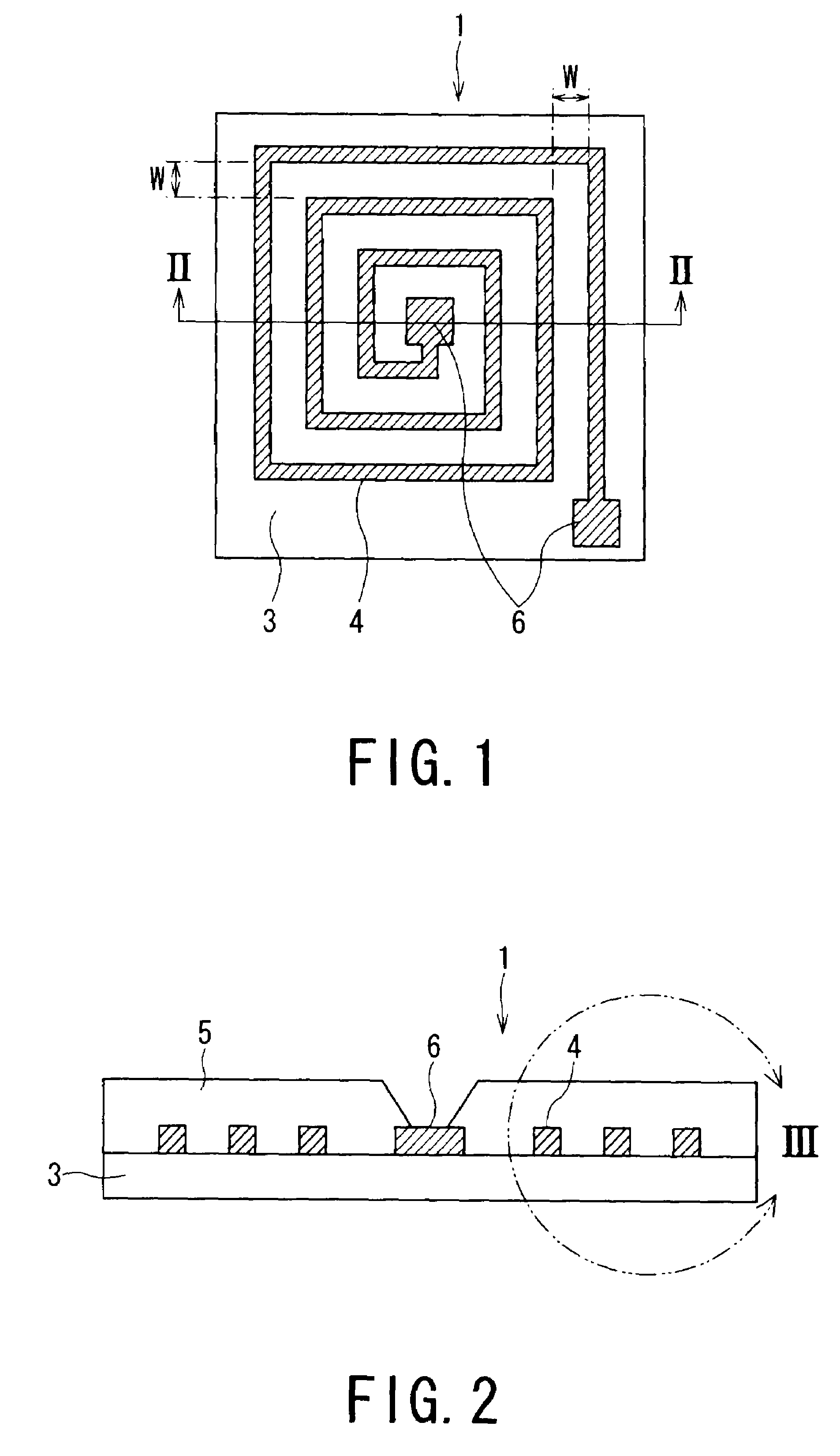
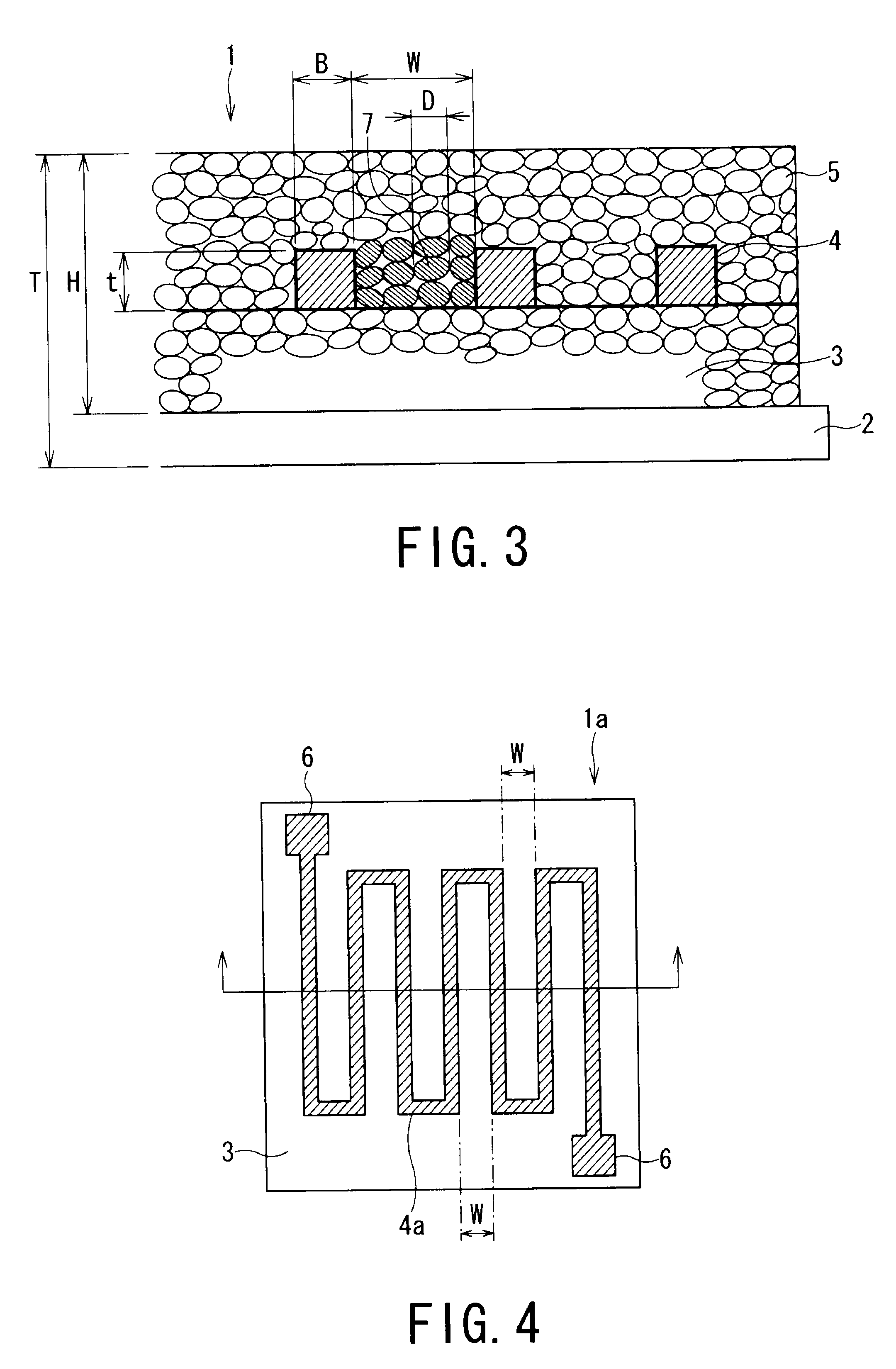
A planar magnetic device 1 including a first magnetic layer 3, a second magnetic layer 5, and a planar coil 4 disposed between the first magnetic layer 3 and the second magnetic layer 5, wherein magnetic particles 7 having a shape ratio S / L of 0.7 to 1 when a length of a long axis is L and a length of a short axis orthogonal to the long axis is L are filled in a gap W between coil wirings of the planar coil 4. According to the planar magnetic device 1, it is possible to realize a planar magnetic device such as an inductor reduced in height by using fine particles that enable to effectively obtain a large inductance value.

Description

TECHNICAL FIELD[0001]The present invention relates to a planar magnetic device (magnetic passive device) used as a thin inductor and, particularly, to a planar magnetic device improved in inductance by increasing magnetic permeability to a magnetic field generated in a planar coil as well as to a power source IC package using the same.BACKGROUND ART[0002]In recent years, various electronic appliances have actively been downsized, and there is a tendency of manufacturing various devices by using a thin film process along with such downsizing. Under the circumstances, as a magnetic device such as an inductor (reactor), a trance, and a magnetic head, there has been proposed a planar magnetic device (flat inductor) having a shell type structure wherein a planar coil having a spiral shape or a zigzag pattern (meander type) coated with a magnetic substance in place of a conventional structure having a bulk magnetic material provided with a coil, and attempts have been made for downsizing ...

Claims


Application Information

Patent Timeline
Patent Type & Authority Patents(United States)
IPC IPC(8): H01F5/00B32B19/00H01F27/28H01F27/24C09D5/23C04B35/00H01F1/00H01F27/02
CPCH01F1/15366H01F1/37H01F17/0006H01L23/645H01L25/165H01F1/26Y10T428/29H01F17/04H01F41/046H01F2017/0066H01F2017/0073H01L2224/48247H01L2924/01078H01L2924/01079H01L2924/19041H01L2924/19104H01L2924/30107H01L2924/3011H01L2924/3025H01L24/48H01L2924/01021Y10S428/928H01L2924/07802H01L2924/00H01L2924/181H01L2224/48091H01L2924/14H01L2924/00014H01L2924/00012H01L2224/45099H01L2224/45015H01L2924/207H01F27/255H01F1/20
Inventor INOUE, TETSUOSATO, AKIRANAKAGAWA, KATSUTOSHI
Owner KK TOSHIBA
Why Eureka
Try Eureka