
Membrane electrode complex and solid type fuel cell using it

a fuel cell and membrane technology, applied in the direction of fuel cell details, cell components, electrochemical generators, etc., can solve the problems of low permeability rate of reaction materials such as fuel and air, unable to make low rr, and water generated at 20° c. is not easily volatilized, etc., to achieve the effect of reducing the performan

Inactive Publication Date: 2010-11-02
TORAY IND INC
View PDF15 Cites 1 Cited by
  • Summary
  • Abstract
  • Description
  • Claims
  • Application Information

AI Technical Summary

Benefits of technology

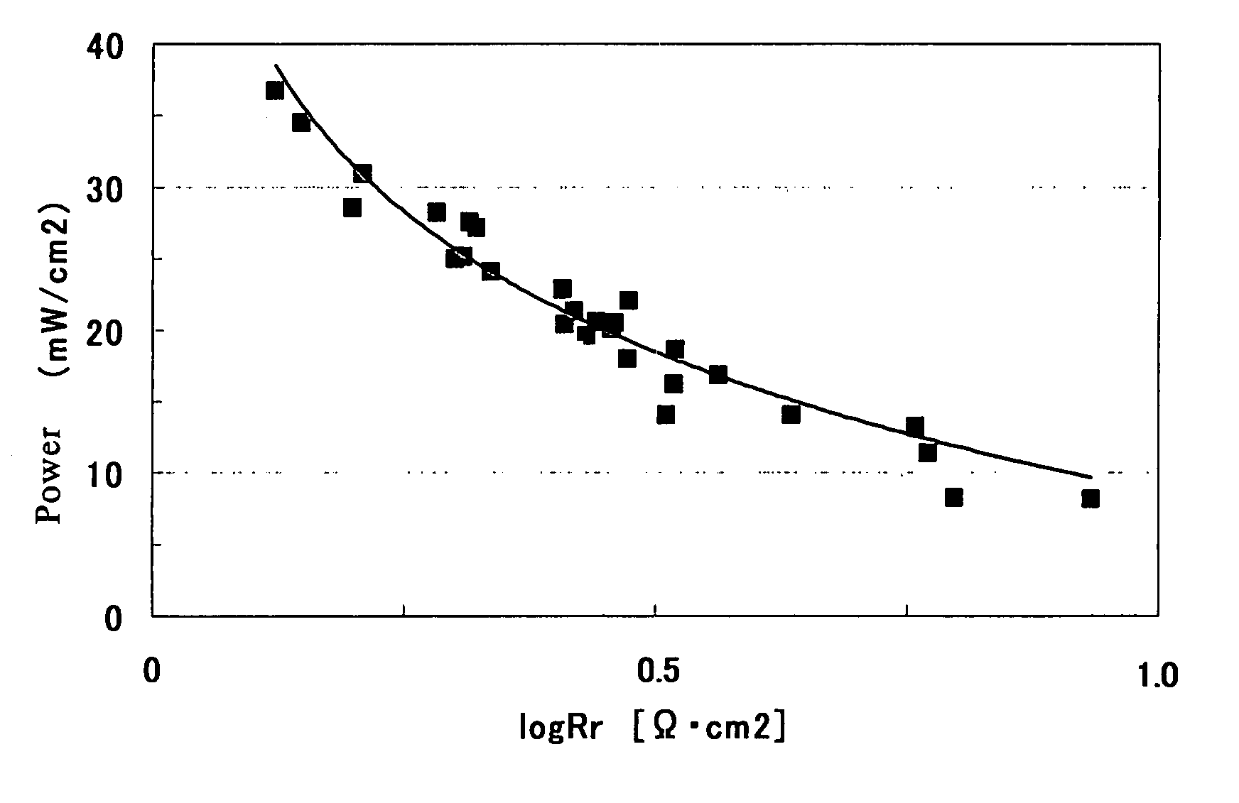
The present invention provides a membrane electrode assembly and a polymer electrolyte membrane fuel cell that can attain a high power and improve the permeability rates of fuel and carbon dioxide. This is achieved by satisfying the following expression: −2≦log Rr<1 or the following expression: −1.5≦log Rr<0.5 The membrane electrode assembly includes an electrocatalyst layer, an anode and a cathode each made of a different material. The thickness of the electrodes and the amount of materials used in the electrodes are optimized to improve the power output and permeability rates of the fuel cell. The membrane electrode assembly can be used in a small-sized polymer electrolyte membrane fuel cell and can be used as a power source for various electric appliances.

Problems solved by technology

Thus, water generated at 20° C. is not easily volatilized, and further the permeability rates of reaction materials, such as fuel and air, or generated carbon dioxide get low.
However, according to the conventional art, the Rr was unable to be made low; thus, the power was not easily improved.

Method used


Image

  • Membrane electrode complex and solid type fuel cell using it
  • Membrane electrode complex and solid type fuel cell using it
  • Membrane electrode complex and solid type fuel cell using it

Examples


example 1

(1) Production of an Anode and a Cathode

[0127]A carbon cloth made of carbon fiber woven cloth and manufactured by E-TEK in USA was treated with 20% PTFE. Specifically, the carbon cloth was immersed into a 20% by weight dispersion of polytetrafluoroethylene, which will be abbreviated to PTFE hereinafter, in water, pulled up therefrom, dried and fired. A carbon black dispersion containing 20% by weight of PTFE was applied onto one surface of the carbon cloth, and the resultant was fired to produce an electrode substrate. Onto this electrode substrate was applied an anode catalyst coating solution composed of Pt—Ru carried carbon catalysts “HiSPEC” (registered trademark) 7000 and “HiSPEC” (registered trademark), 6000 manufactured by Johnson & Matthey Co., a 20% solution of “Nafion” (registered trademark) manufactured by Du Pont Co, and n-propanol. The coating solution was then dried to produce an anode catalyst layer. The application of the anode catalyst coating solution was carried o...

example 2

[0133]In Example 1, the platinum amount in the anode catalyst layer was set to 1.0 mg / cm2. Moreover, the carbon amount, the platinum amount and the ion conductor amount in the cathode catalyst layer, the thickness thereof, and the ratio of the platinum amount to the ionic group amount were changed to conditions shown in Table 2-1. The same method as in Example 1 except these was performed to produce a membrane electrode assembly and evaluate it. The resultant evaluation results of the membrane electrode assembly are shown in Tables 1-1 and 2-1.

example 3

[0134]In Example 1, the platinum amount in the anode catalyst layer was set to 5.0 mg / cm2. Moreover, the carbon amount, the platinum amount and the ion conductor amount in the cathode catalyst layer, the thickness thereof, and the ratio of the platinum amount to the ionic group amount were changed to conditions shown in Table 2-1. The same method as in Example 1 except these was performed to produce a membrane electrode assembly and evaluate it. The resultant evaluation results of the membrane electrode assembly are shown in Tables 1-1 and 2-1.


PUM

PropertyMeasurementUnit
thicknessaaaaaaaaaa
thicknessaaaaaaaaaa
thicknessaaaaaaaaaa

Abstract

A polymer electrolytic material has excellent proton conductivity and excellent fuel shutting property, and accordingly provide a polymer electrolytic fuel cell with a high efficiency. This polymer electrolytic material has an unfreezable water ratio Rw1 defined by the following expression (S1) in a range of 20 to 100% by weight in hydrated state:Rw1=[Wnf / (Wfc+Wnf)]×100  (S1)in which Wnf represents the unfreezable water content per 1 g of the polymer electrolytic material in dry state and Wfc represents the low freezing point water content per 1 g of the polymer electrolytic material in dry state.

Description

TECHNICAL FIELD[0001]The present invention relates to a membrane electrode assembly, and a polymer electrolyte membrane fuel cell using the same.BACKGROUND ART[0002]A fuel cell is usually formed to have, as one unit, a cell wherein: a membrane electrode assembly, which may be abbreviated to an MEA hereinafter, is composed of electrodes of an anode and a cathode, in which reaction for generating electricity is caused, and a polymer electrolyte membrane, which becomes an ion conductor, between the anode and the cathode; and the MEA is sandwiched between separators. The electrodes are composed of: electrode substrates for promoting gas diffusion and performing power collection (feeding), which may be referred to as gas diffusion electrodes or current collectors; and electrocatalyst layers of the anode and the cathode, which are actual electrochemical reaction fields. For example, in the anode of a polymer electrolyte membrane fuel cell, which may be abbreviated to a PEFC hereinafter, a...

Claims


Application Information

Patent Timeline
Patent Type & Authority Patents(United States)
IPC IPC(8): H01M8/10H01M4/86
CPCH01M4/8605H01M4/926H01M8/1004H01M8/1011Y02E60/523Y02E60/50H01M4/86H01M8/02
Inventor KONO, SHUNJIKIDAI, MASAYUKIUETE, TAKAO
Owner TORAY IND INC
Learn More