
Catalyst and process for producing liquefied petroleum gas

a technology of liquefied petroleum gas and catalyst, which is applied in the direction of hydrocarbon preparation catalysts, metal/metal-oxide/metal-hydroxide catalysts, physical/chemical process catalysts, etc., can solve the problems of insufficient activity of the process, insufficient high yield of hydrocarbons, and insufficient low carbon dioxide content of products obtained by the above-mentioned process, so as to prolong the catalyst life, stably produce, and reduce the deterioration

Inactive Publication Date: 2010-11-16
JAPAN GAS SYNTHESIZE
View PDF1 Cites 15 Cited by
  • Summary
  • Abstract
  • Description
  • Claims
  • Application Information

AI Technical Summary

Benefits of technology

"The present invention provides a catalyst for producing a liquefied petroleum gas (LPG) with high activity, selectivity, and yield, using methanol and dimethyl ether as main components. The catalyst includes a Pd- and / or Pt-based catalyst component and a USY-type zeolite. The invention also provides a process for economically producing LPG using the catalyst. The technical effects of this invention include the ability to produce a high yield of LPG with a high activity and selectivity using a simple catalyst and process."

Problems solved by technology

However, the above-mentioned process does not always give a sufficiently high activity (a conversion of carbon monoxide), a sufficiently high yield of a hydrocarbon, and a sufficiently high yield of propane and butane.
Furthermore, a product obtained by the above-mentioned process may not have a sufficiently low carbon dioxide content.
Carbon dioxide is less useful and is hard to be reused, and therefore, it is economically undesirable to yield a large amount of carbon dioxide as a by-product.
However, as is in the process described in the above-mentioned Japanese Patent Laid-open Publication No. 61-23688, this process does not always give a sufficiently high activity (a conversion of carbon monoxide) and a sufficiently high yield of a hydrocarbon, and the obtained product may not have a sufficiently low carbon dioxide content.
However, the above-mentioned process may not give a sufficiently high conversion of methanol to propane and butane.
Furthermore, when using a ZSM-5 / Pt—C Series as a catalyst layer, the deterioration with time of the catalyst may be generally significant and the catalyst life may not be sufficiently long.
Generally, when an olefin is produced from methanol and / or dimethyl ether using a zeolite as a catalyst, the zeolite catalyst is apt to be deteriorated due to coking.

Method used


Image

  • Catalyst and process for producing liquefied petroleum gas
  • Catalyst and process for producing liquefied petroleum gas

Examples


example 1

[0136](Preparation of a Catalyst)

[0137]A mechanically powdered catalyst in which 0.5 wt % of Pd was supported on silica (Pd / SiO2; average particle size: 1 μm) was used as a Pd- and / or Pt-based catalyst component. The catalyst was prepared as follows.

[0138]The silica, which is a support for the Pd- and / or Pt-based catalyst component, was CARIACT G3 (trade name), produced by Fuji Silysia Chemical Ltd. The silica had a specific surface area of 820 m2 / g, as determined by a BET method with N2 as an adsorption gas, using ASAP2010 (Shimadzu Corporation).

[0139]First, the silica was pulverized to 20 to 40 mesh, sized and dried. And then, 8.8 mL of a 50 mg / mL aqueous solution of Pd(NO3)2(NH3)2 was added drop by drop to 20 g of the silica. After sufficiently impregnating the solution into pores, the silica was dried in a drying machine at 120° C. for 12 hours. The above process of impregnation and drying was repeated two more times.

[0140]Then, the silica impregnated with Pd was calcined at 450...

example 2

[0148](Preparation of a Catalyst)

[0149]A catalyst was prepared in the same way as Example 1, except that a proton-type USY zeolite with a SiO2 / Al2O3 ratio of 20 (USY(20)) was used as a USY-type zeolite.

[0150](Production of LPG)

[0151]Using the prepared catalyst, the LPG production reaction was carried out in the same way as Example 1.

[0152]Gas chromatographic analysis of the product indicated that, after three hours from the beginning of the reaction, a conversion of dimethyl ether was 100%, a conversion of dimethyl ether to carbon monoxide was 2.7%, a conversion of dimethyl ether to carbon dioxide was 0.0%, and a conversion of dimethyl ether to a hydrocarbon was 97.3%. The produced hydrocarbon gas contained propane and butane in 65.2% on the basis of carbon. A conversion of dimethyl ether to propane and butane was 63.4% on the basis of carbon.

[0153]The results are shown in Table 1.

example 3

[0154](Preparation of a Catalyst)

[0155]A catalyst was prepared in the same way as Example 1, except that a proton-type USY zeolite with a SiO2 / Al2O3 ratio of 30 (USY(30)) was used as a USY-type zeolite.

[0156](Production of LPG)

[0157]Using the prepared catalyst, the LPG production reaction was carried out in the same way as Example 1.

[0158]Gas chromatographic analysis of the product indicated that, after three hours from the beginning of the reaction, a conversion of dimethyl ether was 99.8%, a conversion of dimethyl ether to carbon monoxide was 2.7%, a conversion of dimethyl ether to carbon dioxide was 0.0%, and a conversion of dimethyl ether to a hydrocarbon was 97.1%. The produced hydrocarbon gas contained propane and butane in 64.3% on the basis of carbon. A conversion of dimethyl ether to propane and butane was 62.4% on the basis of carbon.

[0159]The results are shown in Table 1.

[0160]

TABLE 1Example 1Example 2Example 3CatalystPd / SiO2:USY(10) = 1:2Pd / SiO2:USY(20) = 1:2Pd / SiO2:USY(...


PUM

PropertyMeasurementUnit
specific surface areaaaaaaaaaaa
temperatureaaaaaaaaaa

Abstract

A catalyst for producing a liquefied petroleum gas according to the present invention comprises a Pd- and / or Pt-based catalyst component and a USY-type zeolite. By using the catalyst, a hydrocarbon containing propane or butane as a main component, i.e. a liquefied petroleum gas, can be produced with high activity, high selectivity and high yield from at least one of methanol and dimethyl ether.

Description

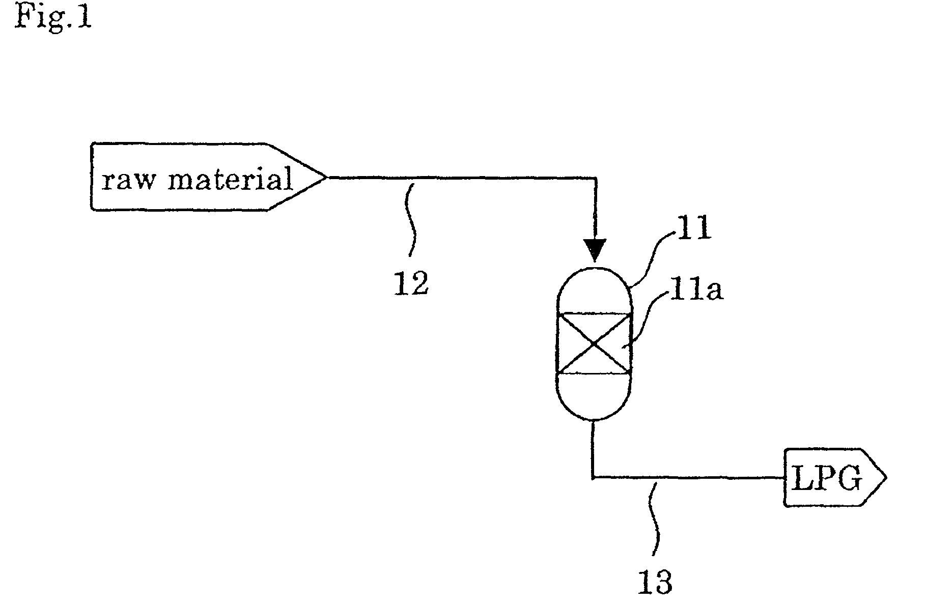
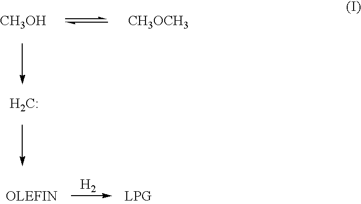
TECHNICAL FIELD[0001]This invention relates to a catalyst for producing a liquefied petroleum gas containing propane or butane as a main component by reacting at least one selected from the group consisting of methanol and dimethyl ether with hydrogen. This invention also relates to a process for producing a liquefied petroleum gas using the catalyst.[0002]Furthermore, this invention relates to a process for producing a liquefied petroleum gas containing propane or butane as a main component from a synthesis gas, via methanol and / or dimethyl ether. This invention also relates to a process for producing a liquefied petroleum gas containing propane or butane as a main component from a carbon-containing starting material such as a natural gas, via methanol and / or dimethyl ether.BACKGROUND OF THE INVENTION[0003]Liquefied petroleum gas (LPG) is a liquefied petroleum-based or natural-gas-based hydrocarbon which is gaseous at an ambient temperature under an atmospheric pressure by compress...

Claims


Application Information

Patent Timeline
Patent Type & Authority Patents(United States)
IPC IPC(8): C07C1/04C07C1/10C07C1/207
CPCB01J23/42B01J23/44B01J29/084B01J35/0006B01J35/023B01J35/1023B01J37/0201B01J37/0236C07C1/20C07C9/08C07C9/10C07C2521/08C07C2523/42C07C2523/44C07C2529/08C07C2529/12Y02P20/582B01J35/19B01J35/617B01J35/40
Inventor FUJIMOTO, KAORUASAMI, KENJILI, XIAOHONGZHANG, QIANWEN
Owner JAPAN GAS SYNTHESIZE
Learn More