Low voltage, two-level, six-pulse induction motor controller driving a medium-to-high voltage, three-or-more-level AC drive inverter bridge

a technology of inverter bridge and inverter, which is applied in the direction of dc-ac conversion without reversal, process and machine control, instruments, etc., can solve the problems of increased complexity of controlling switches, increased costs, and increased complexity of switches

Active Publication Date: 2010-11-16
EATON INTELLIGENT POWER LTD +1
View PDF21 Cites 45 Cited by
  • Summary
  • Abstract
  • Description
  • Claims
  • Application Information

AI Technical Summary

Benefits of technology

[0026]Further aspects, object and advantages will be set forth in the detailed description that follows.

Problems solved by technology

A drawback of a three-level inverter is that while a two-level inverter bridge requires only six semiconductor power switches, a three-level inverter bridge requires twelve switches, thereby increasing costs.
Further increasing costs is that as the number of levels and switches in the inverter bridge is increased, the complexity of controlling the switches also increases.
The signals that drive the switches need to be carefully timed—otherwise the switches may be damaged or destroyed.
This complexity increases the costs of controllers used with multiple-level inverters.
A side-effect of this result is that controllers for multiple-level drives are produced in much lower volume.
These functions are all in addition to motor control, and demand large amounts of expertise and resources to be developed.
As a result of the lower volumes, controllers for multiple-level systems used with medium-and-high voltage drives are more expensive and typically offer less-or-limited interfacing capabilities than corresponding controllers for two-level systems produced for low voltage AC drives.
Unfortunately, common two-level modulator signals from a low-voltage induction motor controllers are not suitable for the control of multi-level inverter bridges.

Method used


Image

  • Low voltage, two-level, six-pulse induction motor controller driving a medium-to-high voltage, three-or-more-level AC drive inverter bridge
  • Low voltage, two-level, six-pulse induction motor controller driving a medium-to-high voltage, three-or-more-level AC drive inverter bridge
  • Low voltage, two-level, six-pulse induction motor controller driving a medium-to-high voltage, three-or-more-level AC drive inverter bridge

Examples


first embodiment

[0076]The first embodiment is a method for implementing this first variation of the invention. As illustrated in FIG. 5, the six modulated signals are converted into N time-coordinated signals (step 500), the N time-coordinated signals being used to control the N switches of a multiple-level inverter bridge (step 510). As illustrated, there is a three-phase, pulse-width modulated output. As explained above, it is required that when the six modulated signals are converted into N time-coordinated signals, for each branch b, never-less-than N / 6 of the time coordinated signals have a logical-off state.

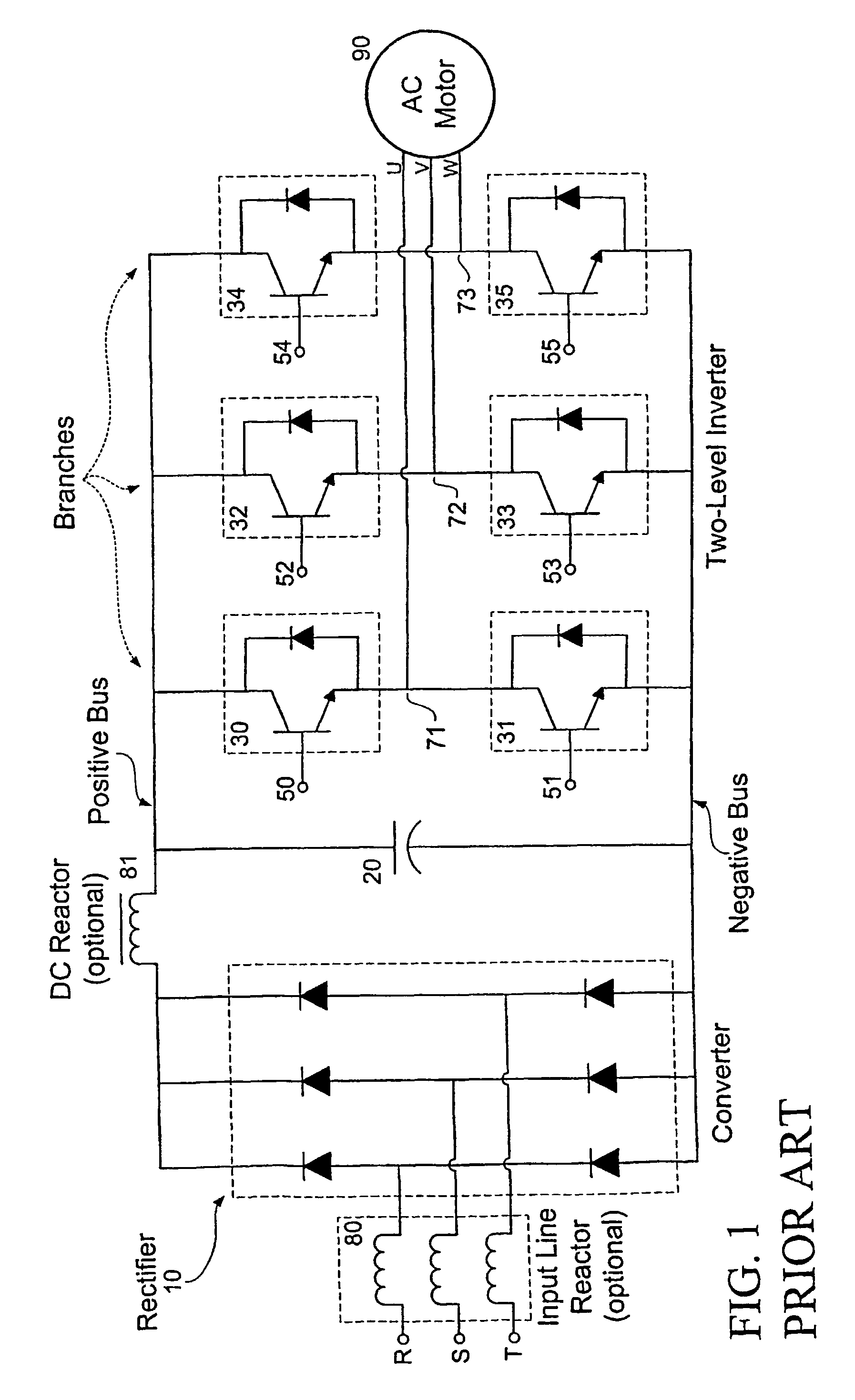
[0077]Since the six modulated signals were originally intended to control three branches of two switches each (FIG. 1), the six modulated signals can be further characterized as being three pairs of modulated signals A1b and A2b. If these modulated signals were used to control a two-level inverter bridge, each pair would control one of the three branches of the two-level bridge. That is, e...

second embodiment

[0104]the invention is an adapter circuit in accordance with the first variation of the invention, converting modulated signals A1b and A2b into time-coordinated signals S1b to S(N / 3)b. The adapter circuit is built from analog and / or digital circuits, and / or programmed into a programmable logic device such as a Digital Signal Processor (DSP), a microcontroller, a microprocessor, or a Complex Programmable Logic Device (CPLD) in accordance with the procedures illustrated in FIGS. 5 to 16 and as discussed above.

[0105]For an analog implementation, any type of delay element can be used, such circuits being numerous, and well known in the art. One example is a timer circuit implemented to create a delay. Another example is a resistor and capacitor in series connected to a voltage comparator amplifier, as illustrated in FIG. 28. The amount of time delay is defined by the values of the resistor and the capacitor. The voltage comparator amplifier compares an analog voltage threshold to the c...

third embodiment

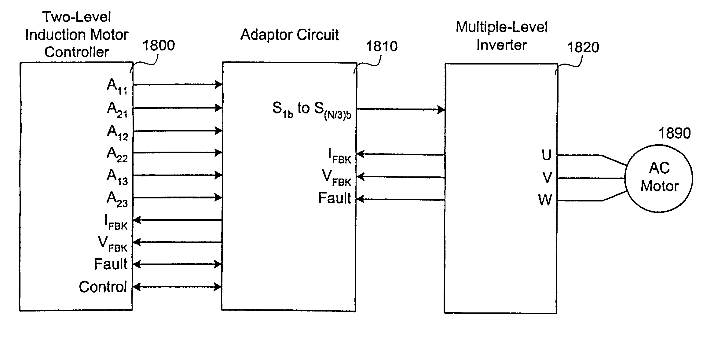
[0109]The third embodiment is an induction motor drive system implementing the first variation of the invention. The induction motor drive includes at least a two-level motor controller outputting signals for controlling a two-level inverter bridge, a multiple-level bridge having N≧12 switches arranged to form 3 branches, and an adapter circuit generating N time-coordinated signals for controlling the N switches of the multiple-level inverter bridge from the signals output by the two-level induction motor controller.

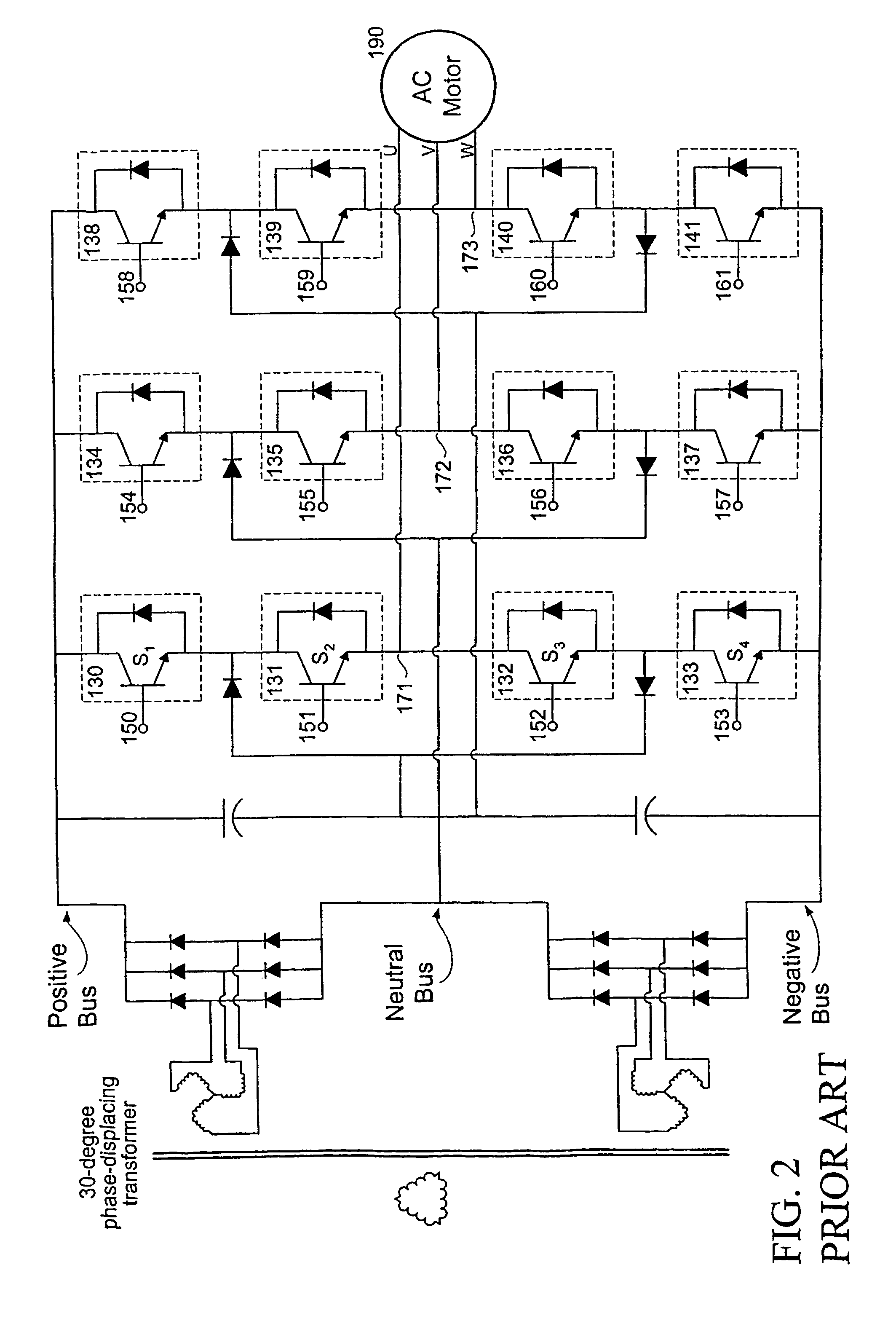
[0110]FIG. 18 illustrates signal flow within the drive system. The two-level induction motor controller 1800 outputs six modulated signals (A1b, A2b), which the adapter circuit 1810 converts into N time-coordinated signals. The N time-coordinated signals control the switches in the N switches in the multiple-level inverter 1820, which provides a three-phase output to an AC motor 1890. For examples of common configurations of the N switches of the multiple-level inverter ...


PUM


Abstract

A method and circuit enabling off-the-shelf controllers designed for use with a two-level AC drive inverter bridge (1920) to drive inverter bridges with three-or-more levels. Signals from an ordinary induction motor controller or a two-level induction motor controller (2200) are used to drive the twelve-or-more switches of a three-or-more level inverter bridge (1920), as are used in medium-and-high voltage applications. The proper sequence and timing of switching for the three-or-more-level inverter bridge is based in-part upon either the output of the six pulse-width modulators, or the output of the flux and torque control device, or the voltage control device (2210), of the two-level controller (2200).

Description

[0001]Priority is claimed from U.S. Provisional Application 60 / 399,355 filed Jul. 31, 2002, and U.S. Provisional Application 60 / 453,817 filed Mar. 12, 2003, both provisional applications being incorporated herein by reference.BACKGROUND OF THE INVENTION[0002]1. Field of the Invention[0003]Operation of an induction motor using a three-or-more level inverter bridge operating under the control of a controller designed for two-level inverter bridges.[0004]2. Description of the Related Art[0005]Induction motor drives, also called AC (alternating current) drives are used to control the speed and torque of multiphase induction motors, which for a long time have been the workhorse of the industry.[0006]Today's AC drives can be divided into two categories: low-voltage and medium-voltage. The low-voltage AC drives are widely used and cover the 0 VAC to 600 VAC range. Low-voltage AC drives are manufactured by almost five hundred companies around the world. Medium-voltage AC drives cover input ...

Claims


Application Information

Patent Timeline
Patent Type & Authority Patents(United States)
IPC IPC(8): H02P7/00H02P27/04H02M7/48H02M7/487H02P27/14
CPCH02M7/487H02P27/14H02M2007/53876H02M7/53876H02P21/00H02P27/04
Inventor NOJIMA, GERALDO
Owner EATON INTELLIGENT POWER LTD
Why Eureka
Try Eureka