Microwave receiver front-end assembly and array

Inactive Publication Date: 2010-11-16
HRL LAB
View PDF9 Cites 243 Cited by
  • Summary
  • Abstract
  • Description
  • Claims
  • Application Information

AI Technical Summary

Benefits of technology

[0013]1. The microwave receiver front-end assembly is based on using an efficient RF-photonic link to sense the incident microwave electromagnetic radiation without needing to absorb the microwave power. The sensor head allows the incident microwave radiation to pass through it or to be reflected from it, with preferably negligible absorption of that radiation. No electricity is carried between the sensor head and the rest of the receiver front end. By passively sensing the electric field components of the electromagnetic field passing through or reflected from the sensor head with an electro-optic material, and by converting the RF signals of that time-varying electric field into a time-varying RF modulation of the light carried in the RF-photonic link, this assembly self-limits the RF signal level that is supplied to the electronic components of the front end and en

Problems solved by technology

Many of today's sophisticated communication radio receivers are extremely sensitive and need to demodulate signals that are well below −100 dBm, that is, less than 100 fW.
While this low signal threshold increases the range between the transmitter and the receiver, it also makes these receivers highly susceptible to destruction by high energy electromagnetic pulses.
The adverse effect of high energy electromagnetic radiation on communication radios has been known for a long time.
Compo

Method used


Image

  • Microwave receiver front-end assembly and array
  • Microwave receiver front-end assembly and array
  • Microwave receiver front-end assembly and array

Examples


Embodiment Construction

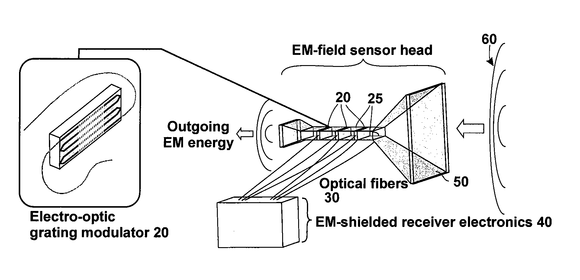
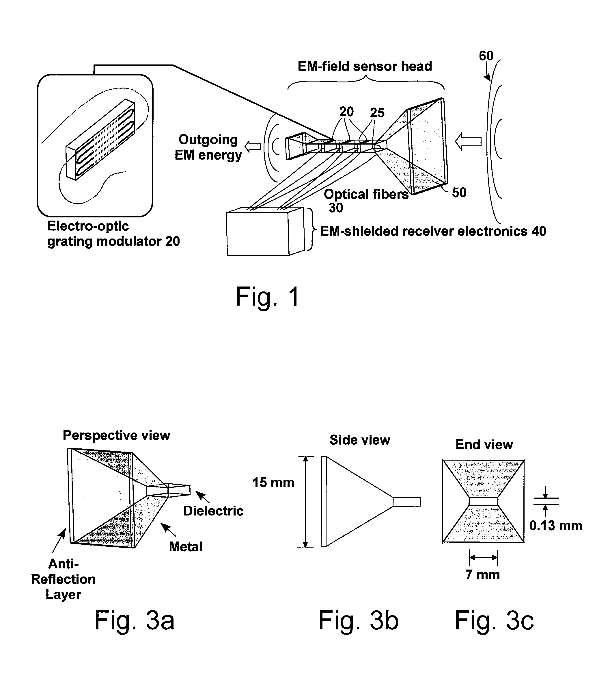
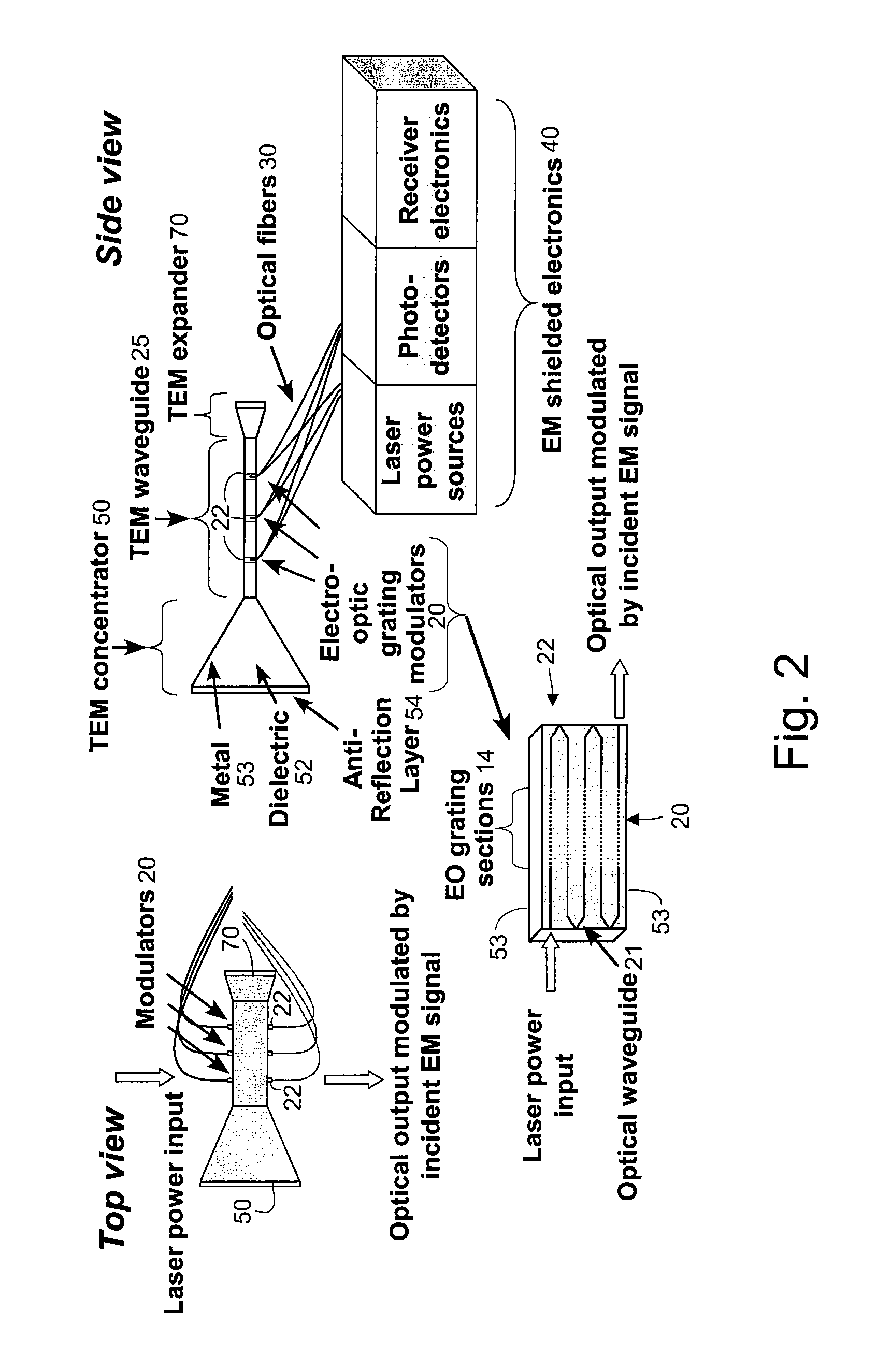
[0038]The technology described in this disclosure addresses the need to maintain high radio sensitivity, while at the same time, insuring tolerance to unwanted high-power, transient electromagnetic radiation. The disclosed microwave front-end assembly (or sensor head) 10 (see FIG. 1) includes a series of high-sensitivity electro-optic (EO) modulators 20. The modulators 20 passively probe the incoming electromagnetic (EM) field, by the field-dependent EO effect, without absorbing its associated EM energy. Optical fibers 30 of the microwave-photonic (MWP) links optically connect the sensor head 10 to a shielded enclosure 40 that protects the receiver electronics therein. As illustrated in FIG. 1, the sensor head 10 consists of a transverse electromagnetic (TEM) horn antenna 50 coupled to a dielectric-filled TEM microwave waveguide 25 containing at least one dielectric EO modulator 20. The design and quantity of the EO modulators 20 provide sufficient degrees of freedom to scale the re...


PUM


Abstract

A method of and apparatus for modulating an optical carrier by an incident electromagnetic field. The electromagnetic field propagates in a dielectric-filled transverse electromagnetic waveguide, At least one slice of an electro-optic material is disposed in the dielectric-filled transverse electromagnetic waveguide, the electro-optic material in the dielectric-filled transverse electromagnetic waveguide having at least one optical waveguide therein which has at least a major portion thereof guiding light in a direction orthogonal with respect to a direction in which the dielectric-filled transverse electromagnetic waveguide guides the incident electromagnetic field. Light is caused to propagate in the at least one optical waveguide in the at least one slice of an electro-optic material in the dielectric-filled transverse electromagnetic waveguide for modulation by the incident electromagnetic field.

Description

CROSS REFERENCE TO RELATED APPLICATIONS[0001]This application is related to the following U.S. patent applications: U.S. Ser. No. 12 / 141,825, filed on Jun. 18, 2008 and entitled “Optoelectronic modulator and electric-field sensor with multiple optical-waveguide gratings”; U.S. Ser. No. 12 / 141,834, filed on Jun. 18, 2008 and entitled “Enhanced Linearity RF Photonic Link”; U.S. Ser. No. 12 / 176,089, filed on the same date as this application and entitled “Parallel Modulator Photonic Link”; and U.S. Ser. No. 12 / 176,114, filed on the same date as this application and entitled “An RF Receiver Front-End Assembly”. The disclosures of each of these related applications are hereby incorporated herein by reference.TECHNICAL FIELD[0002]Disclosed is a wideband electromagnetic (EM) field sensor assembly for a microwave receiver front end. The EM field sensor is sensitive to small microwave signal powers, and makes the front end also resistant to being damaged by unwanted high-power incident EM ra...

Claims


Application Information

Patent Timeline
IPC IPC(8): G02B6/00G02F1/01G02B6/34
CPCG01R29/0885H01Q3/2676H01Q13/02G02F1/2255G02F2001/212G02F2001/213G02F2201/307G02F1/212G02F1/213
Inventor YAP, DANIELSCHAFFNER, JAMES H.SIEVENPIPER, DANIEL F.GEARY, KEVINNG, WILLIE W.GREGOIRE, DANIEL J.COLBURN, JOSEPH S.
Owner HRL LAB
Why Eureka
Try Eureka