
Method and apparatus for testing and evaluating performance of a solar cell

a solar cell and performance technology, applied in the direction of individual semiconductor device testing, optical radiation measurement, instruments, etc., can solve the problems of affecting the photoelectric conversion efficiency the impact of the solar cell module's photoelectric conversion efficiency is bad, and the spread of silicon crystal solar cells is interrupted. , to achieve the effect of high purity, high cost and high cos

Inactive Publication Date: 2010-12-07
NARA INSTITUTE OF SCIENCE AND TECHNOLOGY
View PDF8 Cites 9 Cited by
  • Summary
  • Abstract
  • Description
  • Claims
  • Application Information

AI Technical Summary

Benefits of technology

The present invention provides a method and apparatus for evaluating the performance of a solar cell by using an electroluminescence method. This method and apparatus can easily and accurately detect defects in a solar cell module, without the need for a large-scale facility. It is advantageous over conventional methods because it does not require a scanning probe and can be used on a product completed in manufacturing or on a construction. The invention also provides a maintenance method and system for selectively replacing a poor-performing solar cell element, resulting in high efficiency and low cost.

Problems solved by technology

The in-plane defect remarkably decreases output characteristics of the solar cell elements, which causes bad influence in photoelectric conversion efficiency of the solar cell module.
As a result, spread of the silicon crystal solar cells are interrupted due to decrease in the photoelectric conversion efficiency and an increase in costs which are caused by the decrease in the photoelectric conversion efficiency.
Not only is the substrate crack large in size which occurs so as to cross the substrate, but also generates in minute areas inside the substrate.
The substrate crack causes bad influence to photoelectric conversion functions such as reduction of photoproduction current as a centroid of a recombination of minority carriers, and a rise in series resistance by blocking the current passage.
Many of the faults of external causes generate due to fragility of mechanic intensity and external force (including thermal warp) given to the substrate during the production process of the solar cell.
However, the foregoing EBIC and LBIC devices require a large-scale apparatus to detect the defect of the solar cell.
This causes the need for large sum investment for plant and equipment.
Further, with the EBIC and LBIC devices, there are many limitations in arrangements such that a two-dimensional scanner having a good position decision accuracy and a scanner probe that uses electron beams or lasers are required to measure a two-dimensional distribution of the minority carrier diffusion length, an electron microscope is required so as to irradiate the electron beams, and a multiwavelength light source is required for radiating a laser beam.
As such, a problem exists such that the method for evaluating the solar cell module is not easily carried out.
Moreover, a device which analyzes an exothermic distribution from the solar cell has poor sensitivity and resolving power.
Therefore, the defects occurring in the solar cell cannot be accurately detected.
Furthermore, with the technique of detecting the substrate crack by detecting the light leakage, it is not possible to detect minute cracks in which light does not leak, that is, so-called hair cracks, micro cracks and the like.
Development of an evaluation method and the like which contributes to high performance of the polycrystalline solar cell is an immediate issue, in which various defects in the solar cell are detected.

Method used


Image

  • Method and apparatus for testing and evaluating performance of a solar cell
  • Method and apparatus for testing and evaluating performance of a solar cell
  • Method and apparatus for testing and evaluating performance of a solar cell

Examples


example

[0181]An Si solar cell element made from polycrystalline silicon semiconductor was analyzed by passing a forward current in a range of 5 to 40 mA / cm2. In the present Example, an emission microscope (Hamamatsu Photonics K.K. PHEMOS-200) was used. Images picturing the Si solar cell element through which the current was passed are illustrated in FIGS. 7(a) and 7(b). FIG. 7(a) is a view illustrating a light emitting state of an Si solar cell element. FIG. 7(b) is an optical photograph of an electrode shape and the like on the surface. In FIG. 7(a), an electroluminescence (EL) light emission is observed caused by electric flow induced from an electrode. Particle fields and defects which are not observed in a regular optical photograph are clearly seen in the EL light emission image.

[0182]Images taken of a state of the Si solar cell element in a size of 1 cm×1 cm at the time when electric flow is induced are illustrated in FIGS. 8(a) and 8(b). FIG. 8(a) illustrates light emission from the...


PUM


Abstract

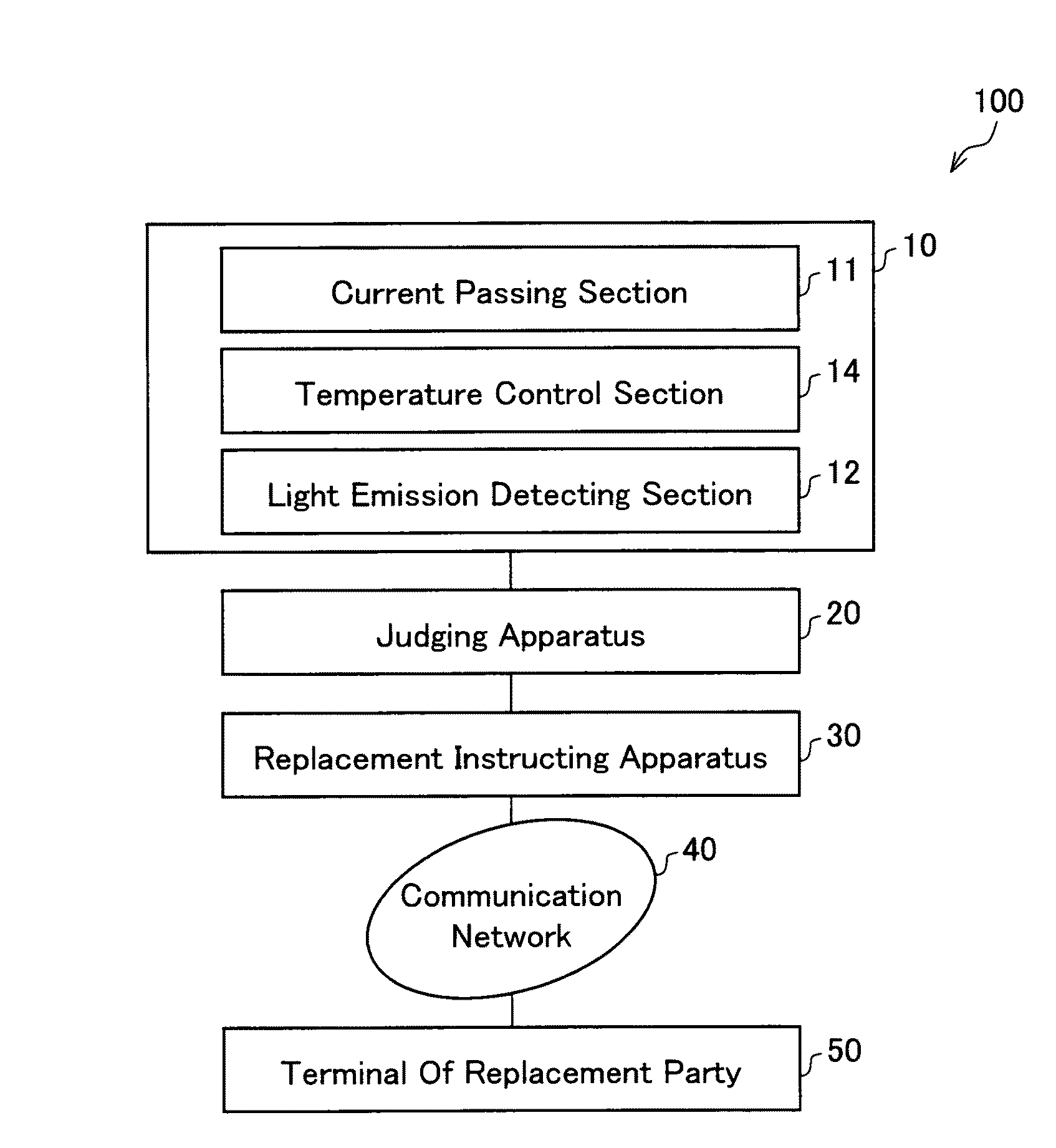
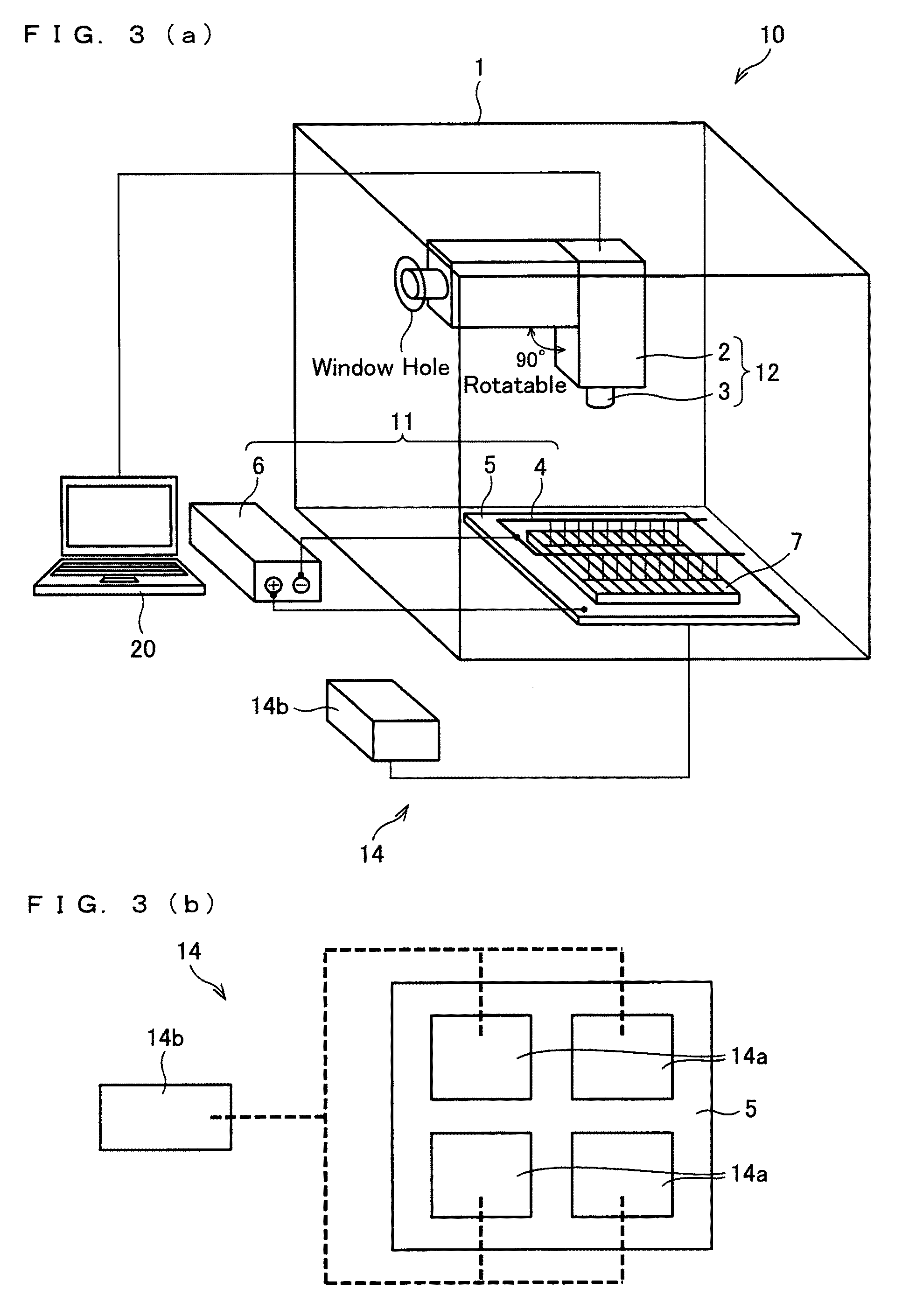
A method for evaluating performance of a solar cell, comprising: a current passing step (S1) of passing, in a forward direction, a direct current with respect to a solar cell element constituting the solar cell; a temperature control step (S2) of heating the solar cell element and controlling a heating temperature of the solar cell element; and a light emission detecting step (S3) of detecting light emission characteristics of light generated from the solar cell element due to the passing of the direct current in the current passing step and the heating of the solar cell element in the temperature control step (S2).

Description

[0001]This application is the U.S. national phase of International Application No. PCT / JP2007 / 058989 filed, 25 Apr. 2007, which designated the U.S. and claims priority to Japanese Application No(s) 2006-128278 filed 2 May 2006, the entire contents of each of which are hereby incorporated by reference.TECHNICAL FIELD[0002]The present invention relates to (i) a method and (ii) an apparatus for easily and accurately evaluating a solar cell in terms of photoelectric conversion performance without a use of a large-sized detection apparatus or the like and (iii) use thereof. Especially, the present invention relates to (I) a method and (II) an apparatus for easily and accurately evaluating a solar cell in terms of photoelectric converting performance by passing an electric current through solar cell elements (e.g., a solar cell module, solar cell panel, or solar cell element per se) constituting the solar cell, and analyzing light emission characteristics due to the electric current passa...

Claims


Application Information

Patent Timeline
Patent Type & Authority Patents(United States)
IPC IPC(8): H01J7/24G01R31/00G01J1/44
CPCH02S50/10Y02E10/50
Inventor FUYUKI, TAKASHI
Owner NARA INSTITUTE OF SCIENCE AND TECHNOLOGY
Learn More