Flip-chip light emitting diodes and method of manufacturing thereof
a light-emitting diode and flip-chip technology, which is applied in the manufacture of semiconductor/solid-state devices, semiconductor devices, electrical devices, etc., can solve the problems of low light-utilization efficiency, reduced device life, and difficulty in high-brightness light-emitting devices, so as to improve luminous efficiency and life span, improve ohmic contact properties, and increase the efficiency of wire bonding and yield
- Summary
- Abstract
- Description
- Claims
- Application Information
AI Technical Summary
Benefits of technology
Problems solved by technology
Method used
Image
Examples
first embodiment
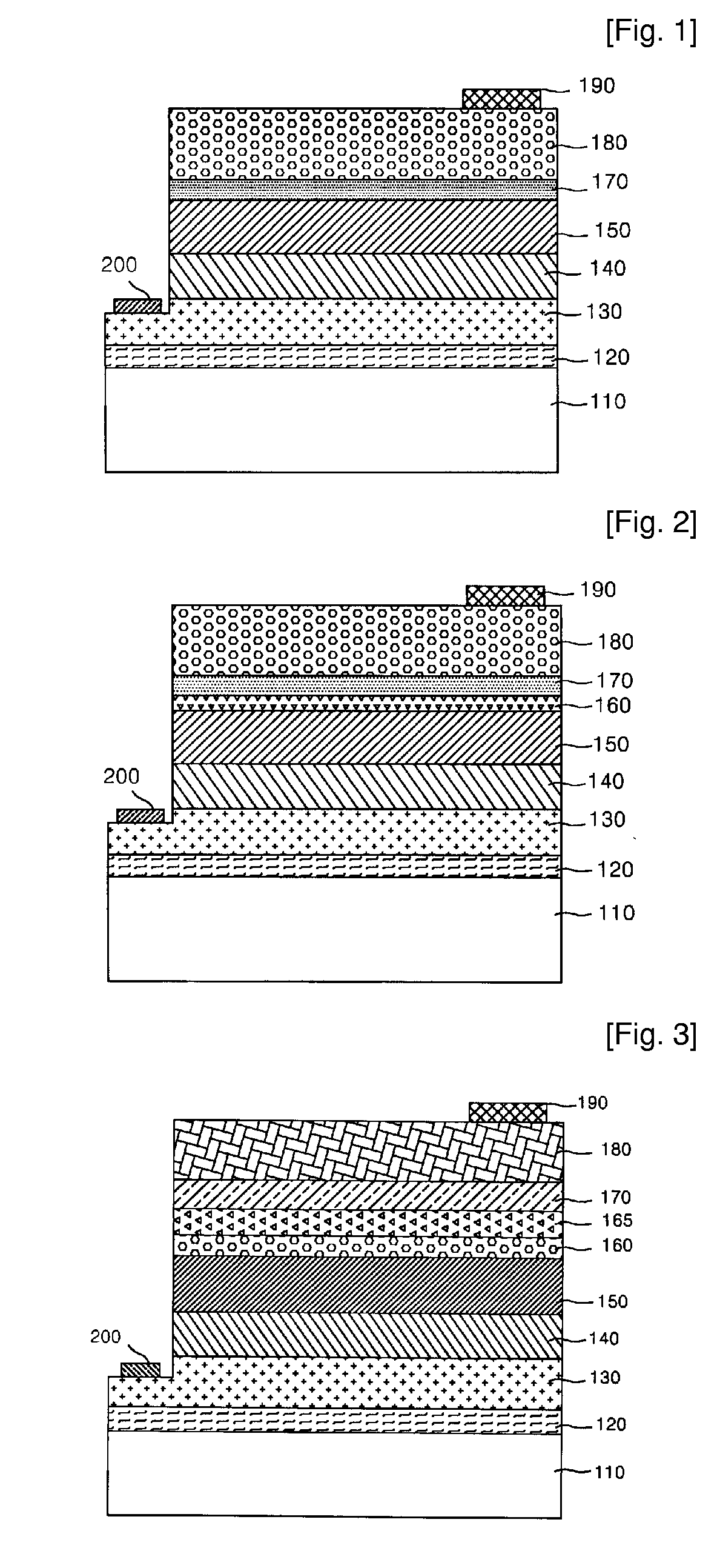
[0050]FIG. 1 shows a cross-sectional view of a flip-chip nitride-based light emitting device in accordance with the present invention.
[0051]Referring now to FIG. 1, the flip-chip nitride-based light emitting device is formed of a structure including a substrate 110, a buffer layer 120, an n-type clad layer 130, an active layer 140, a p-type clad layer 150, a transparent conductive thin film layer 170 and a reflective layer 180 sequentially stacked thereon. Reference numerals 190 and 200 represent a p-type electrode pad and an n-type electrode pad, respectively.
[0052]Parts from the substrate 110 to the p-type clad layer 150 correspond to a light emitting structure, and the transparent conductive thin film layer 170 stacked on the p-type clad layer 150 corresponds to an ohmic contact structure.
[0053]The substrate 110 is preferably formed of any one material selected from sapphire (Al2O3), silicon carbide (SiC), silicon (Si) and gallium arsenide (GaAs).
[0054]The buffer layer 120 may be...
third embodiment
[0111]FIG. 3 shows a cross-sectional view of a flip-chip nitride-based light emitting device in accordance with the present invention. For elements having the same function as in the previously shown drawing, like numbers refer to like elements hereinafter.
[0112]Referring now to FIG. 3, the flip-chip light emitting device is formed of a structure including a substrate 110, a buffer layer 120, an n-type clad layer 130, an active layer 140, a p-type clad layer 150, an interface modification layer 160, an insert metal layer 165, a transparent conductive thin film layer 170 and a reflective layer 180 sequentially stacked thereon.
[0113]Herein, the interface modification layer 160, insert metal layer 165 and transparent conductive thin film layer 170 correspond to a multi-ohmic contact layer.
[0114]The insert metal layer 165 is formed between the interface modification layer 160 and transparent conductive thin film layer 170.
[0115]The insert metal layer 165 is preferably made up of a metal...
fourth embodiment
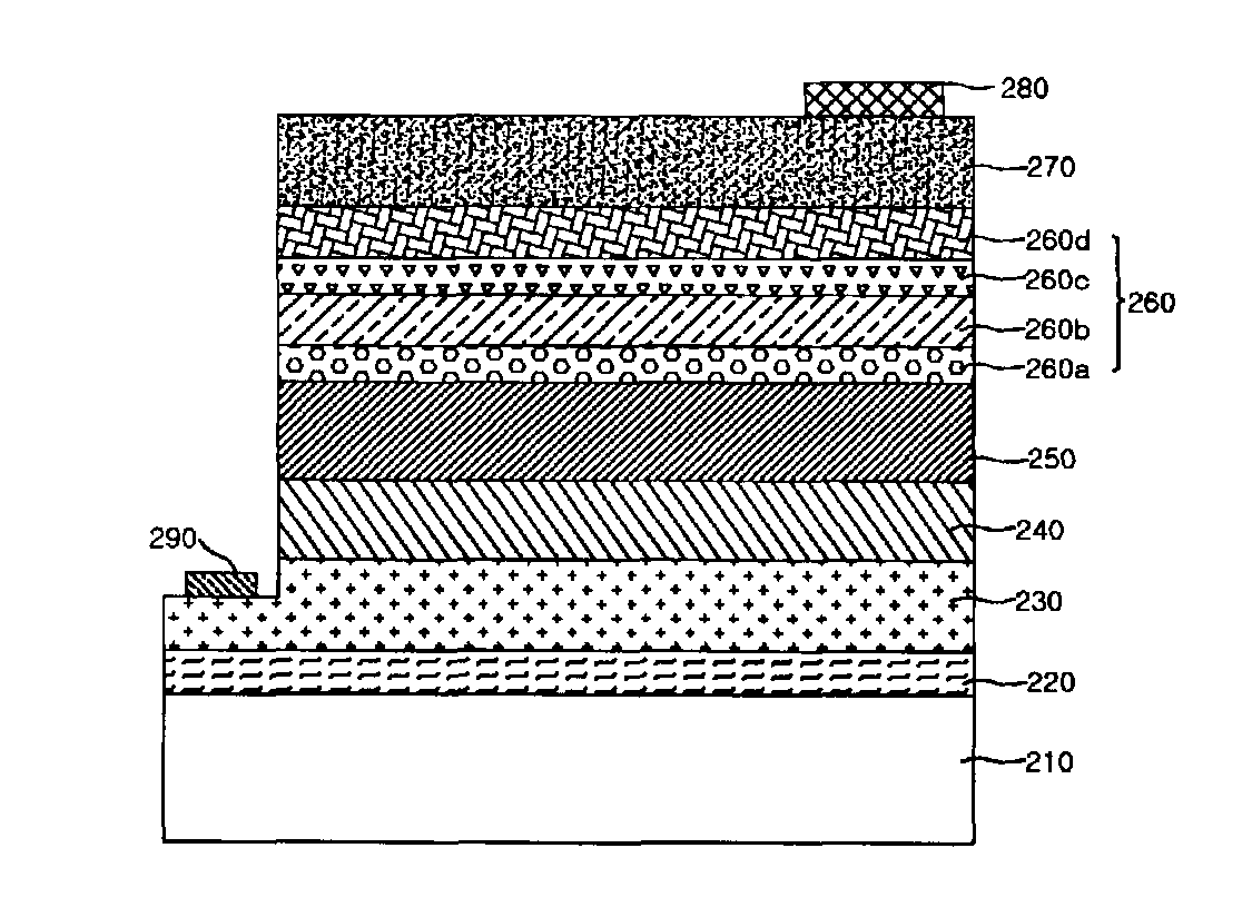
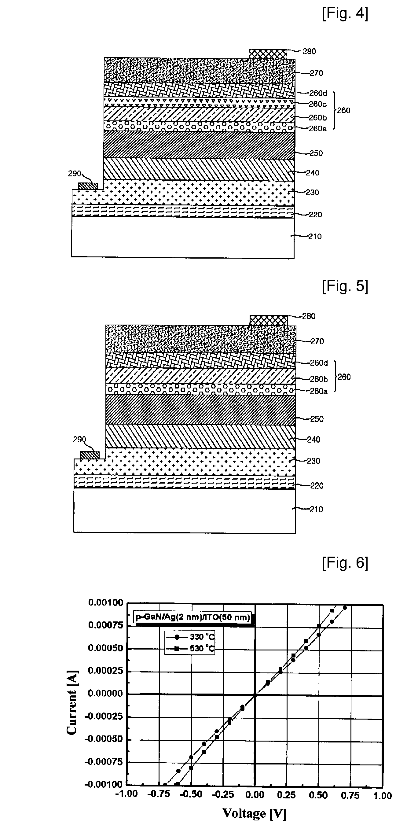
[0134]FIG. 4 shows a cross-sectional view of a flip-chip light emitting device in accordance with the present invention. Referring now to FIG. 4, the flip-chip light emitting device is formed of a structure including a substrate 210, a buffer layer 220, an n-type clad layer 230, an active layer 240, a p-type clad layer 250, a multi-ohmic contact layer 260 and a reflective layer 270 sequentially stacked thereon. Reference numerals 280 and 290 represent a p-type electrode pad and an n-type electrode pad, respectively.
[0135]Since the constituents of such a flip-chip light emitting device are substantially the same as in the first embodiment, except for the multi-ohmic contact layer 260, the detailed description thereof will be omitted. Hereinafter, the multi-ohmic contact layer 260 will be described.
[0136]The multi-ohmic contact layer 260 is formed by repeatedly stacking an interface modification layer 260a / transparent conductive thin film layer 260b as a stack unit. An example of such...
PUM
| Property | Measurement | Unit |
|---|---|---|
| thickness | aaaaa | aaaaa |
| thickness | aaaaa | aaaaa |
| thickness | aaaaa | aaaaa |
Abstract
Description
Claims
Application Information
 - R&D
- Intellectual Property
- Life Sciences
- Materials
- Tech Scout
- Unparalleled Data Quality
- Higher Quality Content
- 60% Fewer Hallucinations
Browse by: Latest US Patents, China's latest patents, Technical Efficacy Thesaurus, Application Domain, Technology Topic, Popular Technical Reports.
© 2025 PatSnap. All rights reserved.Legal|Privacy policy|Modern Slavery Act Transparency Statement|Sitemap|About US| Contact US: help@patsnap.com


