Compact atomic magnetometer and gyroscope based on a diverging laser beam

a gyroscope and laser beam technology, applied in the field of magnetometers and gyroscope methods and systems, can solve the problems of 1 nt/hz, cs magnetometers are large, expensive and difficult to operate, and suffer from considerably worse sensitivity, etc., to achieve high compactness, reduce low-frequency noise, and reduce cost

Inactive Publication Date: 2011-01-18
RGT UNIV OF CALIFORNIA +1
View PDF15 Cites 64 Cited by
  • Summary
  • Abstract
  • Description
  • Claims
  • Application Information

AI Technical Summary

Benefits of technology

[0015]The above and other aspects of the invention can be achieved as will now be briefly described. The innovation the present invention brings to the development of gyroscopes and magnetometers is associated with the diverging beam geometry. This geometry allows a simple, highly compact implementation of the NMR gyroscope that could be fabricated at a much lower cost than gyroscopes of equivalent sensitivity. Additional advantages are the use of differential detection that will reduce the low-frequency noise and improve the angle-random walk, as compared with detection methods that do not allow for differential detection.

Problems solved by technology

These instruments require cryogenic cooling and therefore are large, expensive and difficult to operate.
The cost of Cs magnetometers is higher than all but SQUID-based sensors.
Proton magnetometers, another type of atomic magnetic sensor, are less expensive than Cs magnetometers and are also more accurate, but suffer from considerably worse sensitivity, ˜1 nT / √Hz.
Search coil magnetic sensors can achieve sub-pT sensitivities at high frequencies (>1 MHz) but are largely insensitive to DC magnetic fields.
They are also magnetic, which makes them difficult to use in arrays.
Finally, Hall probe magnetometers have very poor sensitivity (100 nT / √Hz) but are inexpensive.
This is particularly important for applications on moving platforms since platform motion adds considerable noise to a vector sensor as the angle between the field and the sensor axis changes.
One very high performance commercial gyroscope is the hemispherical resonator gyroscope (HRG), which achieves an exceptional angle-random walk (ARW) and bias drift but is very expensive to manufacture.
MEMS gyroscopes generally have very poor bias stability.

Method used


Image

  • Compact atomic magnetometer and gyroscope based on a diverging laser beam
  • Compact atomic magnetometer and gyroscope based on a diverging laser beam
  • Compact atomic magnetometer and gyroscope based on a diverging laser beam

Examples


Embodiment Construction

[0031]The particular values and configurations discussed in these non-limiting examples can be varied and are cited merely to illustrate embodiments of the present invention and are not intended to limit the scope of the invention.

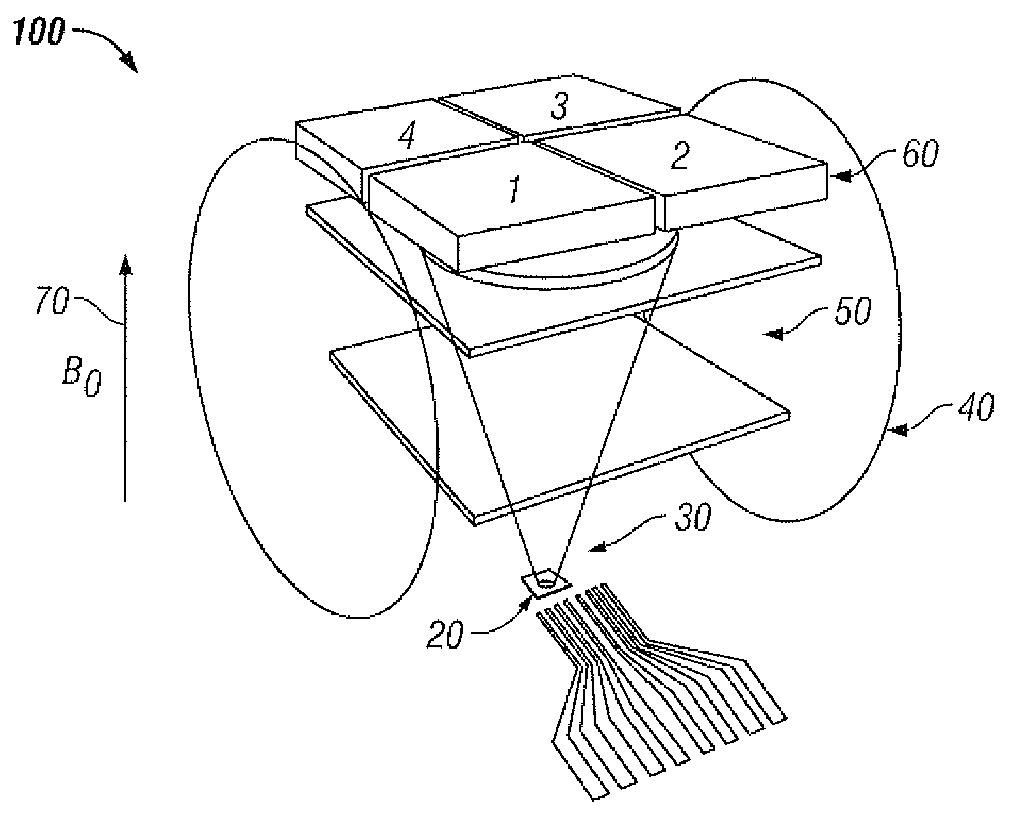
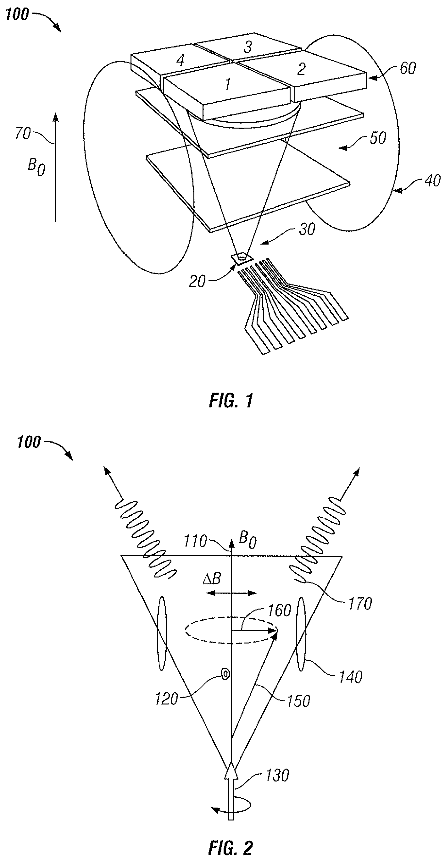
[0032]FIG. 1 illustrates a schematic of an apparatus in which one embodiment of the present invention can be implemented. Shown in the figure is an atomic magnetometer, which could also be operated as a gyroscope under suitable conditions 10. Light is emitted from a semiconductor laser 20, such as a vertical-cavity surface emitting laser (VCSEL). It passes through some optics 30 that makes the laser polarization circular, and that may also attenuate the light beam and change its spatial mode. The light then enters an alkali vapor cell 50 with some divergence. The vapor cell contains alkali atoms at their vapor pressure, along with a buffer gas such as N2 or Ne, which prevents frequent collisions of the alkali atoms with the cell walls. In the gyroscope imp...


PUM


Abstract

An atomic magnetometer that simultaneously achieves high sensitivity, simple fabrication and small size. This design is based on a diverging (or converging) beam of light that passes through an alkali atom vapor cell and that contains a distribution of beam propagation vectors. The existence of more than one propagation direction permits longitudinal optical pumping of atomic system and simultaneous detection of the transverse atomic polarization. The design could be implemented with a micro machined alkali vapor cell and light from a single semiconductor laser. A small modification to the cell contents and excitation geometry allows for use as a gyroscope.

Description

CROSS-REFERENCE TO PROVISIONAL PATENT APPLICATION[0001]This patent application claims priority to U.S. Provisional Patent Application Ser. No. 60 / 954,555, entitled “Compact Atomic Magnetometer and Gyroscope Based on a Diverging Laser Beam,” which was filed on Aug. 7, 2007, the disclosure of which is incorporated herein by reference in its entirety.TECHNICAL FIELD[0002]Embodiments are generally related to magnetometers and gyroscope methods and systems. Embodiments are also related to the field of sensing magnetic fields.BACKGROUND OF THE INVENTION[0003]Magnetometers are used for sensing magnetic fields. Applications include geophysical surveying, nuclear magnetic resonance (magnetic resonance imaging), magneto-cardiography, magneto-encephalography and perimeter surveillance. Gyroscopes sense rotation. These instruments are used in inertial navigation and platform stabilization (anti-roll systems in cars, for example). The implementations described here allow for high sensitivity and...

Claims


Application Information

Patent Timeline
Patent Type & Authority Patents(United States)
IPC IPC(8): G01V3/00
CPCG01C19/60G01R33/26
Inventor KITCHING, JOHNDONLEY, ELIZABETH A.HODBY, ELEANORSHKEL, ANDREIEKLUND, ERIK JESPER
Owner RGT UNIV OF CALIFORNIA
Why Eureka
Try Eureka