Integrated nitride and silicon carbide-based devices

a silicon carbide and integrated technology, applied in the direction of semiconductor devices, electrical equipment, transistors, etc., can solve the problems of limited power handling capability of previously known jfets, large heat generation of high power and high frequency transistors, and limited power handling capability of such devices at higher operating frequencies. achieve the effect of high electron mobility transistor

Active Publication Date: 2011-01-25
MACOM TECH SOLUTIONS HLDG INC
View PDF83 Cites 112 Cited by
  • Summary
  • Abstract
  • Description
  • Claims
  • Application Information

AI Technical Summary

Problems solved by technology

Previously, bipolar transistors and power metal-oxide semiconductor field effect transistors (MOSFETs) have been used for high power applications but the power handling capability of such devices may be limited at higher operating frequencies.
Junction field-effect transistors (JFETS) were commonly used for high frequency applications but the power handling capability of previously known JFETs may also be limited.
In turn, high power and high frequency transistors usually generate larger amounts of heat than low power transistors.
Although these devices provided increased operating frequencies and moderately increased power handling capability, the relatively low breakdown voltage and the lower thermal conductivity of these materials have limited their usefulness in high power applications.
However, such devices have typically required that the piezoelectric crystal be bonded onto a semiconductor substrate (such as silicon) on which active electronic components are formed.
The width and spacing of IDT fingers (and thus the finger period) is limited by the resolution of photolithographic techniques.
However, in the past it has proved difficult to provide multiple device types on a common substrate due to the different epitaxial semiconductor structures required for different types of devices.

Method used


Image

  • Integrated nitride and silicon carbide-based devices
  • Integrated nitride and silicon carbide-based devices
  • Integrated nitride and silicon carbide-based devices

Examples


Embodiment Construction

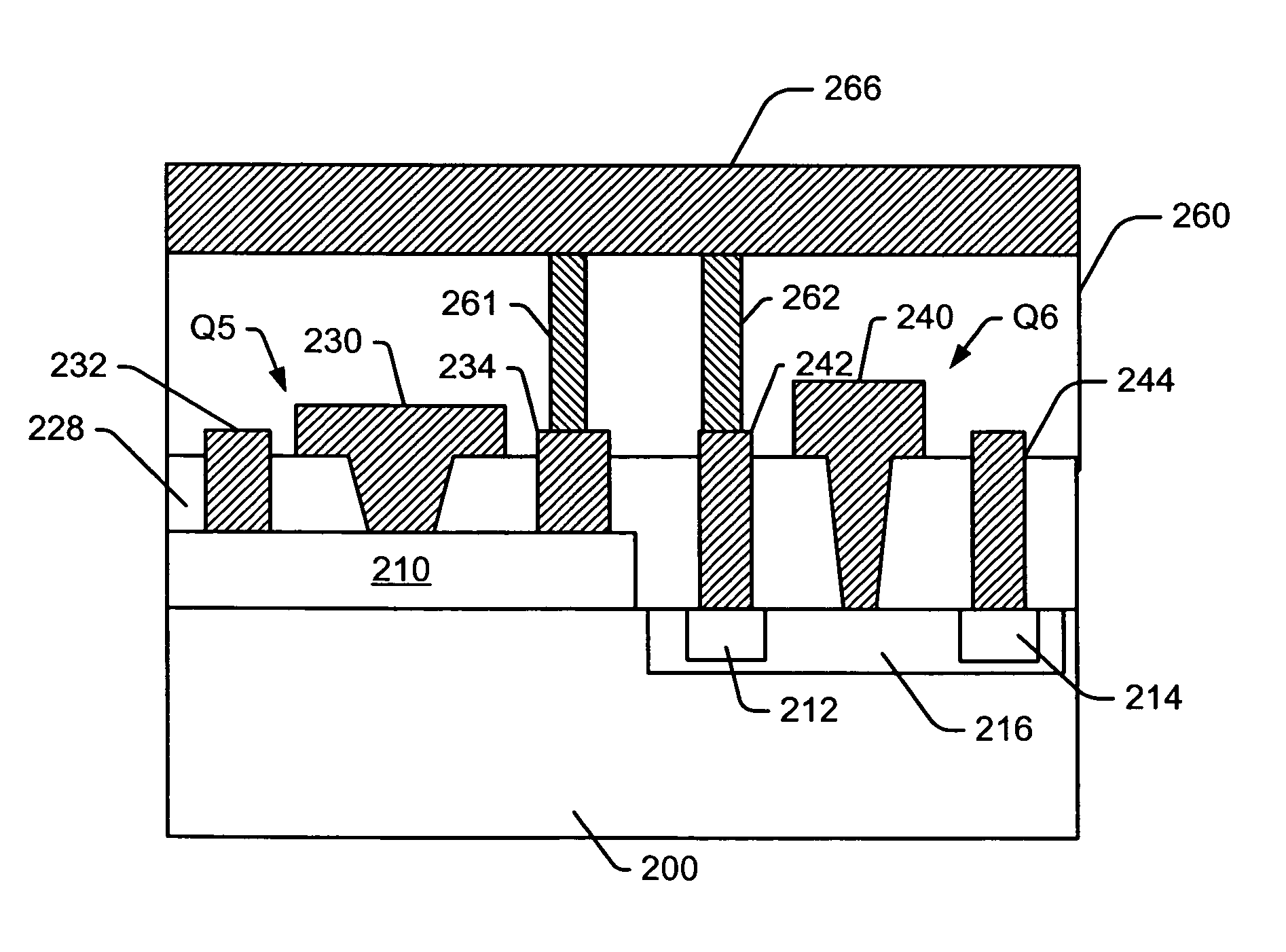
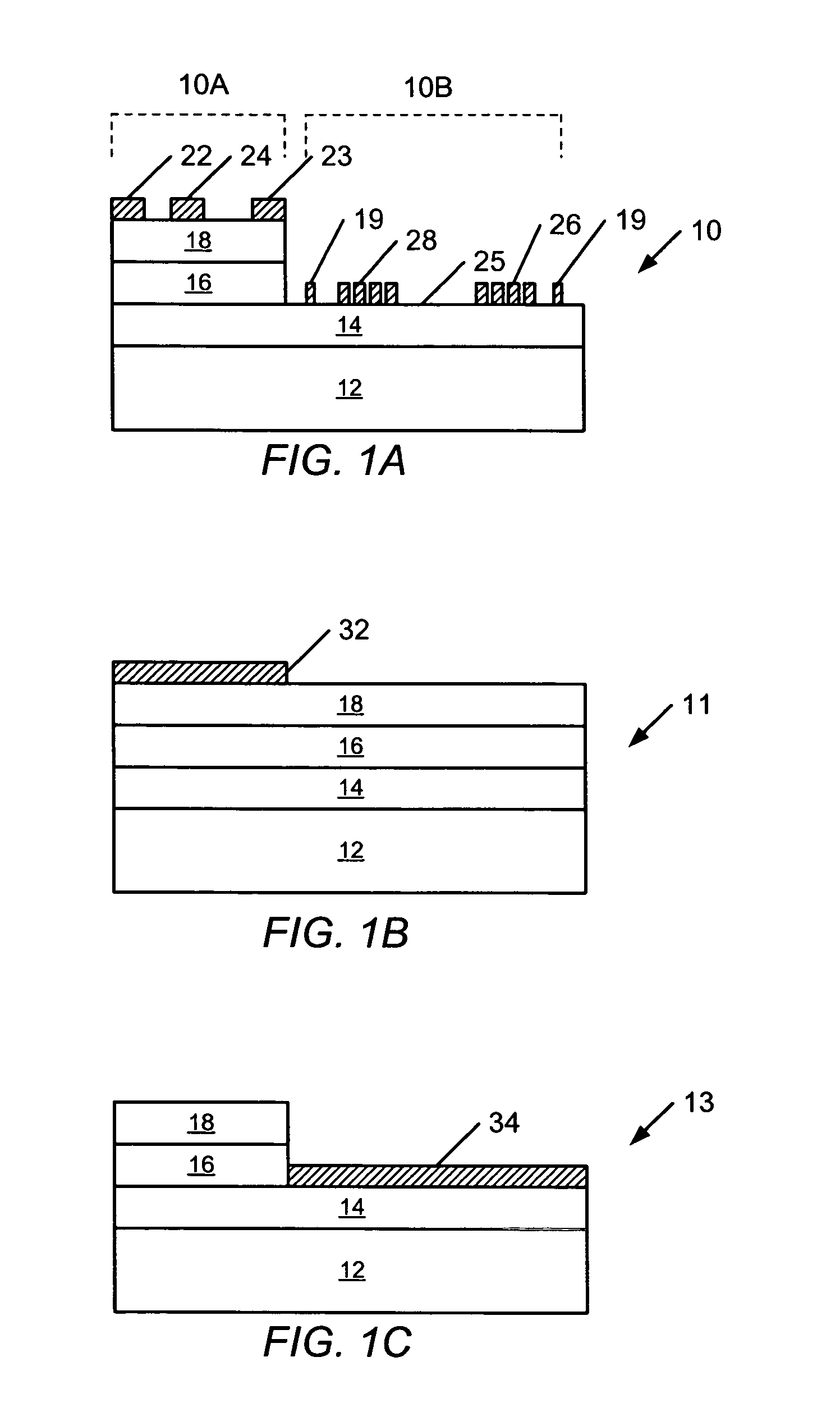
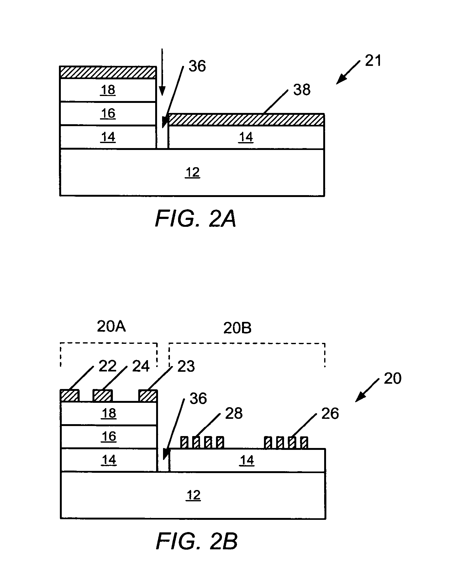
[0073]The present invention now will be described more fully hereinafter with reference to the accompanying drawings, in which various embodiments of the invention are shown. This invention may, however, be embodied in many different forms and should not be construed as limited to the embodiments set forth herein; rather, these embodiments are provided so that this disclosure will be thorough and complete, and will fully convey the scope of the invention to those skilled in the art. Like numbers refer to like elements throughout. Furthermore, the various layers and regions illustrated in the figures are illustrated schematically. Accordingly, the present invention is not limited to the relative size and spacing illustrated in the accompanying figures. As will also be appreciated by those of skill in the art, references herein to a layer formed “on” a substrate or other layer may refer to the layer formed directly on the substrate or other layer or on an intervening layer or layers f...


PUM

PropertyMeasurementUnit
pressureaaaaaaaaaa
temperatureaaaaaaaaaa
bandgapaaaaaaaaaa

Abstract

A monolithic electronic device includes a first nitride epitaxial structure including a plurality of nitride epitaxial layers. The plurality of nitride epitaxial layers include at least one common nitride epitaxial layer. A second nitride epitaxial structure is on the common nitride epitaxial layer of the first nitride epitaxial structure. A first plurality of electrical contacts is on the first epitaxial nitride structure and defines a first electronic device in the first nitride epitaxial structure. A second plurality of electrical contacts is on the first epitaxial nitride structure and defines a second electronic device in the second nitride epitaxial structure. A monolithic electronic device includes a bulk semi-insulating silicon carbide substrate having implanted source and drain regions and an implanted channel region between the source and drain regions, and a nitride epitaxial structure on the surface of the silicon carbide substrate. Corresponding methods are also disclosed.

Description

CLAIM OF PRIORITY[0001]This application claims priority under 35 U.S.C. §120 as a continuation-in-part application of U.S. patent application Ser. No. 10 / 378,331, filed on Mar. 3, 2003 now U.S. Pat. No. 7,112,860, the disclosure of which is hereby incorporated by reference herein as if set forth in its entirety.FIELD OF THE INVENTION[0002]The present invention relates to nitride-based devices. In particular, the present invention relates to the monolithic integration of different types of nitride-based devices on a common substrate, and resulting devices.BACKGROUND[0003]Wide bandgap semiconductor materials, including Group III-nitrides, such as gallium nitride, aluminum gallium nitride, indium nitride and alloys thereof, and silicon carbide, are desirable materials for the fabrication of high power, high temperature and / or high frequency devices. These wide bandgap materials have high electric field breakdown strengths and high electron saturation velocities as compared to other sem...

Claims


Application Information

Patent Timeline
Patent Type & Authority Patents(United States)
IPC IPC(8): H01L29/80H01L21/338H01L27/20H01L41/22H01L41/311H03H3/08H03H9/02H03H9/05H03H9/145
CPCH01L27/20H03H3/08H03H9/02228H03H9/02574H03H9/02976H03H9/0542H10N39/00H03H9/02
Inventor SHEPPARD, SCOTT T.SAXLER, ADAM WILLIAMSMITH, THOMAS
Owner MACOM TECH SOLUTIONS HLDG INC
Why Eureka
Try Eureka