Transparent window pane provided with a resistive heating coating

Inactive Publication Date: 2011-02-01
SAINT-GOBAIN GLASS FRANCE
View PDF12 Cites 21 Cited by
  • Summary
  • Abstract
  • Description
  • Claims
  • Application Information

AI Technical Summary

Benefits of technology

[0059]It is also possible to straddle, with a region of low resistance or with conducting strands, one or more communication windows produced along the edge of the glazing in the c

Problems solved by technology

However, the region may have a high resistance in cer

Method used


Image

  • Transparent window pane provided with a resistive heating coating
  • Transparent window pane provided with a resistive heating coating
  • Transparent window pane provided with a resistive heating coating

Examples


Embodiment Construction

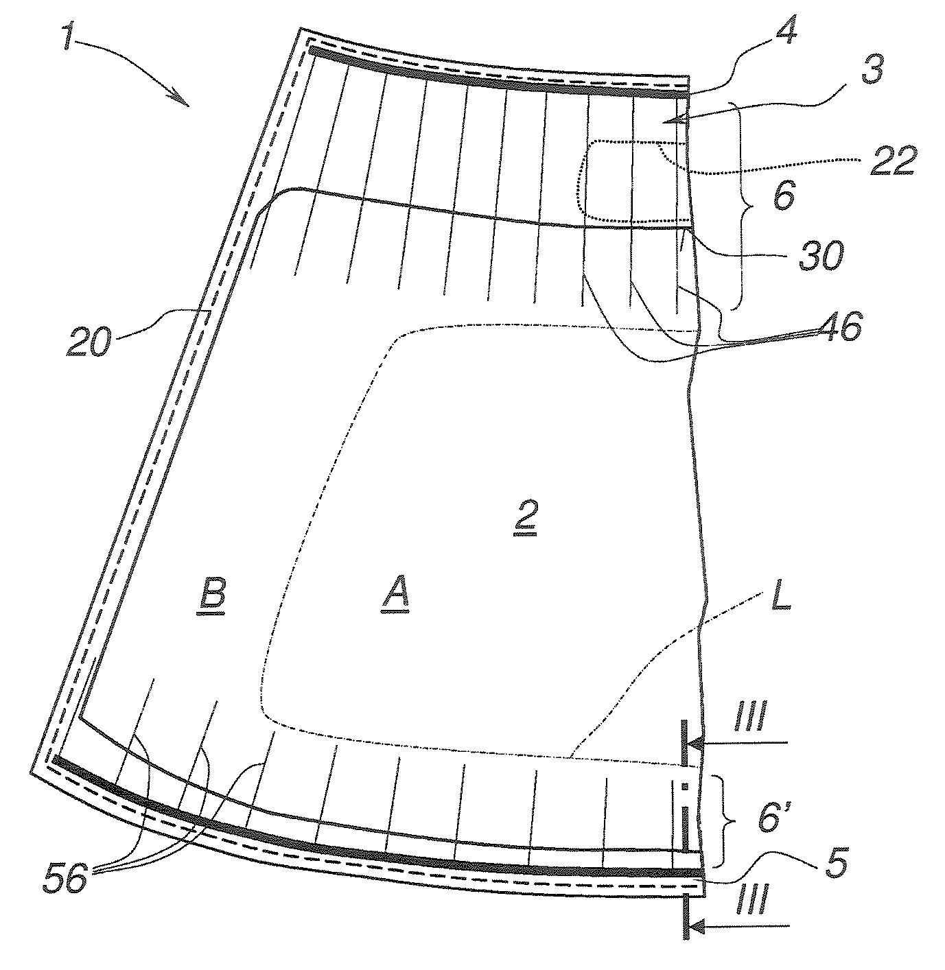
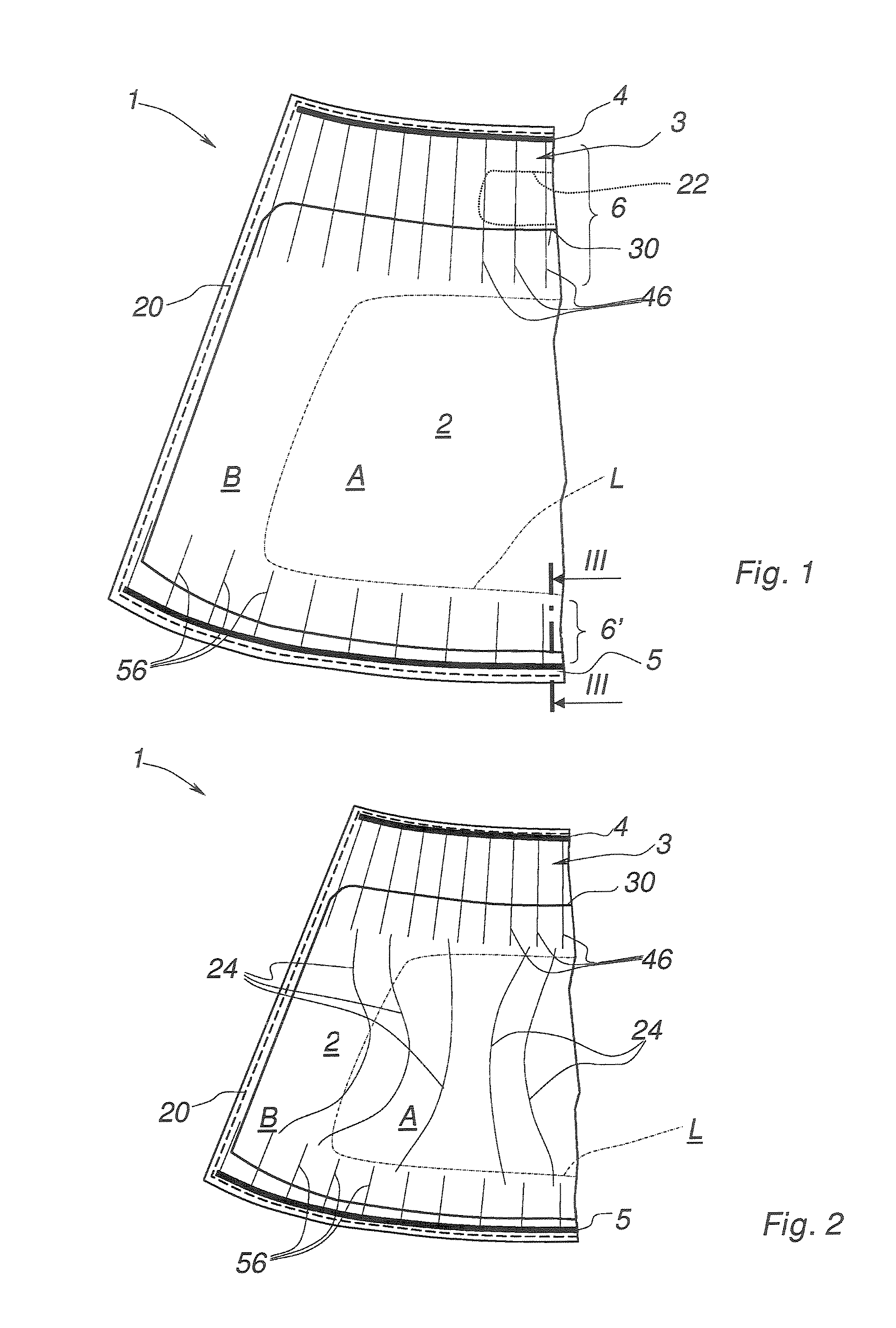
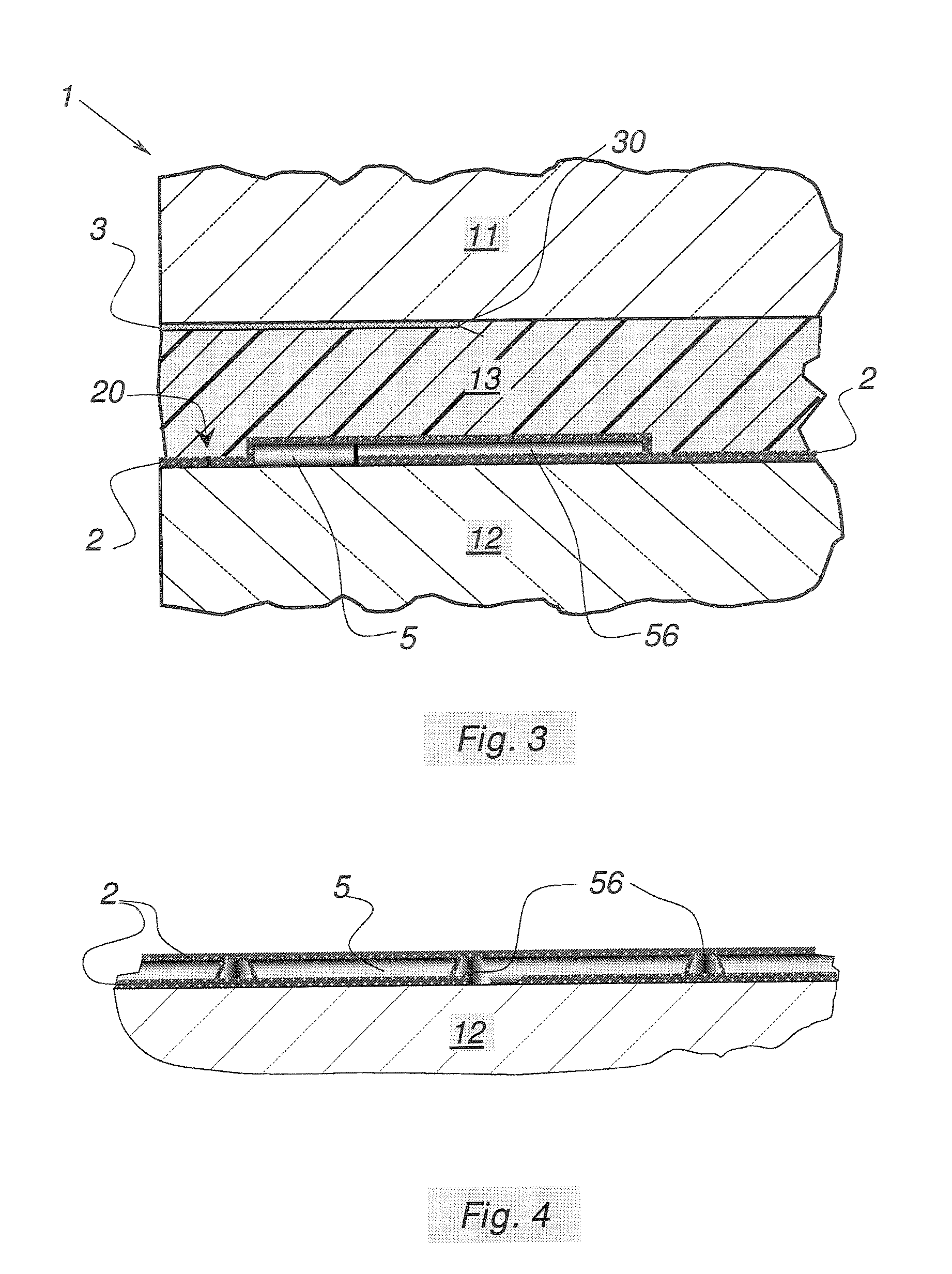
[0069]In the figures, an electrically resistive transparent coating 2 is placed over the entire surface in a manner known per se in a heated laminated glazing unit 1 having an essentially trapezoidal (curvilinear) outline. The glazing unit 1 has been shown here only in one half—its other half is equivalent.

[0070]The coating 2 is deposited in a known manner on a main face of a substrate 11, this substrate then being integrated into the glazing unit 1.

[0071]A broken line denoted by 20 indicates that the outer edge of the continuously coated surface lies all around, but slightly set back toward the inside of, the peripheral outer edge of the laminated glazing unit 1, that is to say an edge band is provided in the coating all around the surface. Thus, the coating is, on the one hand, electrically isolated from the outside and, on the other hand, protected against any corrosion damage penetrating via the outer edge of the glazing. The outer edge 20 may be set back by removing the coating...


PUM


Abstract

The inventive transparent window pane is provided with a resistive heating coating (2) which extends through a substantial portion of the window pane, in particular on a main view field (A) and is electrically connected to at least two conductor rails (4, 5) in such a way that, when an electric' supply voltage is applied between said conductor rails, a circulating current heats the coating heating field, wherein said heating field comprises at least one semi-resistive area (6) directly contacting at least on e conductor rail (4, 5).

Description

BACKGROUND[0001]The invention relates to a transparent glazing unit with a resistive heating coating.[0002]The invention relates more particularly to a glazing unit whose resistive heating coating is a coating placed on a substrate and having thermal insulation and / or solar protection capabilities. The glazing units incorporating this type of coating, when they are intended for equipping vehicles, make it possible in particular to reduce the air-conditioning load and / or reduce excessive overheating (“solar control” glazing) and / or reduce the amount of energy dissipated to the outside (“low-e” or “low-emissivity” glazing) brought about by the ever growing use of glazed surfaces in vehicle passenger compartments.[0003]One type of multilayer known for giving substrates such properties consists of at least two metal layers, such as a silver-based layer, each being placed between two coatings made of a dielectric. This multilayer is generally obtained by a succession of deposition operat...

Claims


Application Information

Patent Timeline
IPC IPC(8): B60L1/02
CPCB32B17/10036B32B17/10183H05B3/84B32B17/10385H05B2203/013H05B2203/008
Inventor SCHMIDT, LOTHARBAUBET, CAROLEMAURER, MARC
Owner SAINT-GOBAIN GLASS FRANCE
Why Eureka
Try Eureka