Nanowire structures comprising carbon

a technology of nanowires and carbon, which is applied in the direction of non-metal conductors, cell components, sustainable manufacturing/processing, etc., can solve the problems of large quantity of expensive platinum (and/or ruthenium) catalysts, low efficiency and power density, and inability to embrace dmfcs, etc., to achieve high electrical connectivity, low overall diffusion resistance, and high structural stability

Active Publication Date: 2011-05-10
ONED MATERIAL INC
View PDF96 Cites 143 Cited by
  • Summary
  • Abstract
  • Description
  • Claims
  • Application Information

AI Technical Summary

Benefits of technology

[0021]In another embodiment, the present invention provides a proton exchange membrane fuel cell with nanostructured components, in particular, one or more of the electrodes of the membrane electrode assembly. The nanostructured fuel cell has a higher catalytic metal utilization rate at the electrodes, higher power density (kW / volume and kW / mass), and lower cost than conventional fuel cells. The nanostructured fuel cells are not only attractive for stationary and mobile applications, but also for use as a compact power supply for microelectronics such as laptops, cell phones, cameras and other electronic devices.
[0022]In accordance with a further embodiment of the present invention, nanowires (e.g., inorganic nanowires) for use in a membrane electrode assembly of a fuel cell are disclosed which generally comprise a metal catalyst deposited on a surface of the nanowires. The metal catalyst may be deposited as a thin film on the surface of the nanowires, or as a layer of catalyst particles, e.g., by functionalizing the surface of the nanowires with standard surface chemistries. Suitable metal catalysts include, but are not limited to, one or more of platinum (Pt), ruthenium (Ru), iron (Fe), cobalt (Co), gold (Au), chromium (Cr), molybdenum (Mo), tungsten (W), manganese (Mn), technetium (Tc), rhenium (Re), osmium (Os), rhodium (Rh), iridium (Ir), nickel (Ni), palladium (Pd), copper (Cu), silver (Ag), zinc (Zn), tin (Sn), aluminum (Al), and combinations and alloys thereof (such as bimetallic Pt:Ru nanoparticles). The nanowires may comprise branched structures (e.g., side nodules) to increase the surface area to volume ratio of the wires to maximize the catalytic efficiency of the fuel cell. The nanowires may be made from metallic conducting, semiconducting, carbide, nitride, or oxide materials such as RuO2, SiC, GaN, TiO2, SnO2, WCx, MoCx, ZrC, WNx, MoNx etc. It is preferable that the nanowires be made from a material that is resistant to degradation in a weak acid so that the nanowires are compatible with the reactants of a variety of different fuel cells.
[0024]In this way, the intimate relationship between the nanowire catalyst support and the polymer shell ensures that most, if not all, of the metal catalyst particles are located at a three-phase contact point (e.g., such that the catalyst particles are accessible to the fuel cell reactants, electrolyte and nanowire core for efficient electron and proton conduction). The controlled nanowire surface chemistry can be used to control the wettability of the polymer in the composite nanowire structure and ensures that catalyst particles are exposed and accessible for catalysis.
[0027]The nanowires in the nanowire network are preferentially physically and / or electrically connected to one or more other wires in the network to form an open, highly branched, porous, intertwined structure, with low overall diffusion resistance for reactants and waste diffusion, high structural stability and high electrical connectivity for the electrons to ensure high catalytic efficiency, thus leading to high power density and lower overall cost. The multiple electrical connectivity of the nanowires ensures that if one wire breaks or is damaged in the system, for example, that all points along the wire still connect to the anode (or cathode) electrode along different paths (e.g., via other nanowires in the network). This provides substantially improved electrical connectivity and stability as compared to previous packed particle composite structures. The catalyst is highly accessible to the fuel source to produce electrons and protons, while the electrons can conduct directly to the bipolar plate through the nanowire and the protons can transport directly to the membrane through the polymer.
[0028]The nanowires in the network of nanowires may be cross-linked or fused together using various cross-linking or sintering methods described further herein at points where such nanowires contact or are proximal to others of the nanowires to increase the connectivity and structural stability of the nanowire network. In another embodiment, the same strategy of cross-linking or sintering can be used to improve the electrical or structural connectivity between the nanowires and catalyst material that is in contact or proximal with such nanowires.

Problems solved by technology

Initially developed in the early 1990s, DMFCs were not embraced because of their low efficiency and power density, as well as other problems.
One of the drawbacks of the DMFC is that the low-temperature oxidation of methanol to hydrogen ions and carbon dioxide requires a more active catalyst, which typically means a larger quantity of expensive platinum (and / or ruthenium) catalyst is required.
Thus, most DMFCs which utilize packed particle composite structures are highly inefficient.
In addition, connectivity to the anode and / or cathode is currently limited in current packed particle composite structures due to poor contacts between particles and / or tortuous diffusion paths for fuel cell reactants between densely packed particles.

Method used


Image

  • Nanowire structures comprising carbon
  • Nanowire structures comprising carbon
  • Nanowire structures comprising carbon

Examples


example 1

Preparation of Nanowire Structures

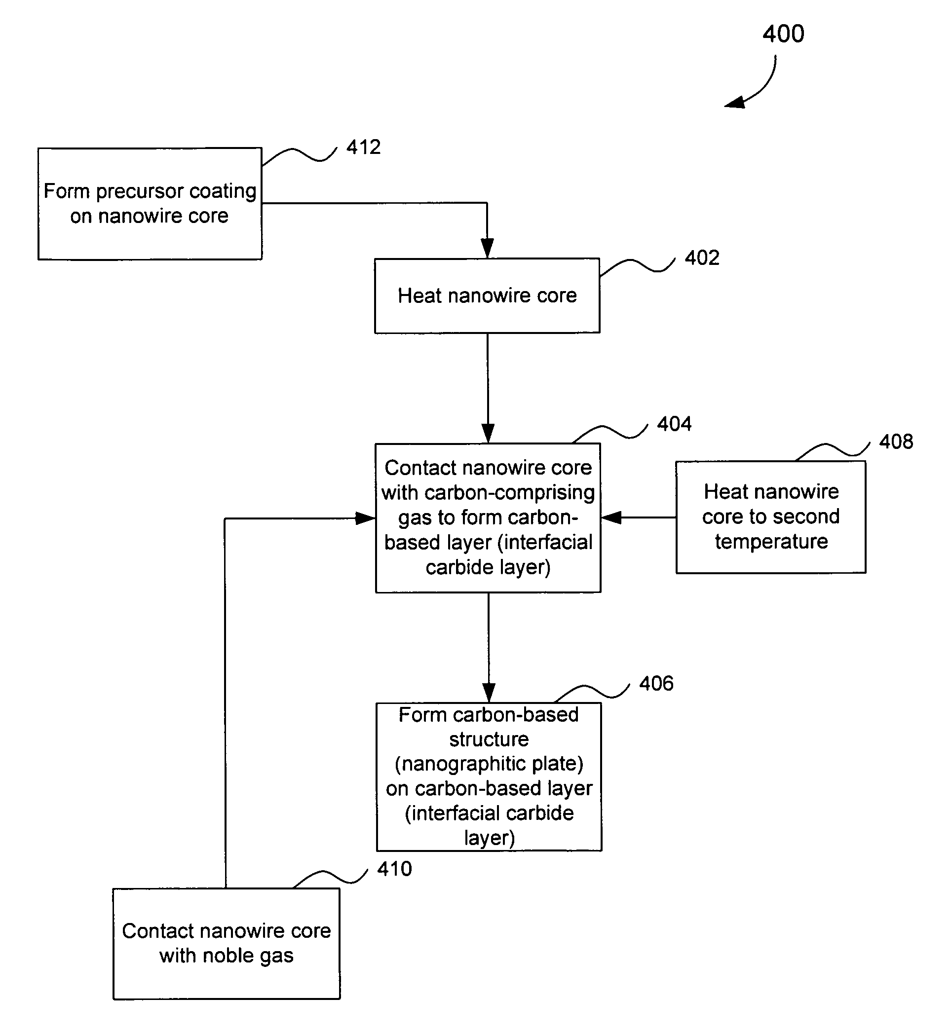
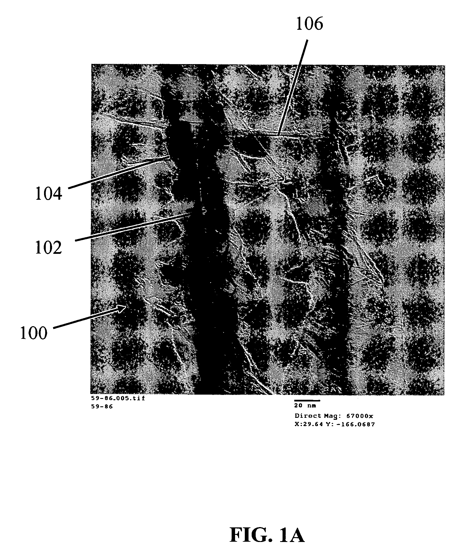
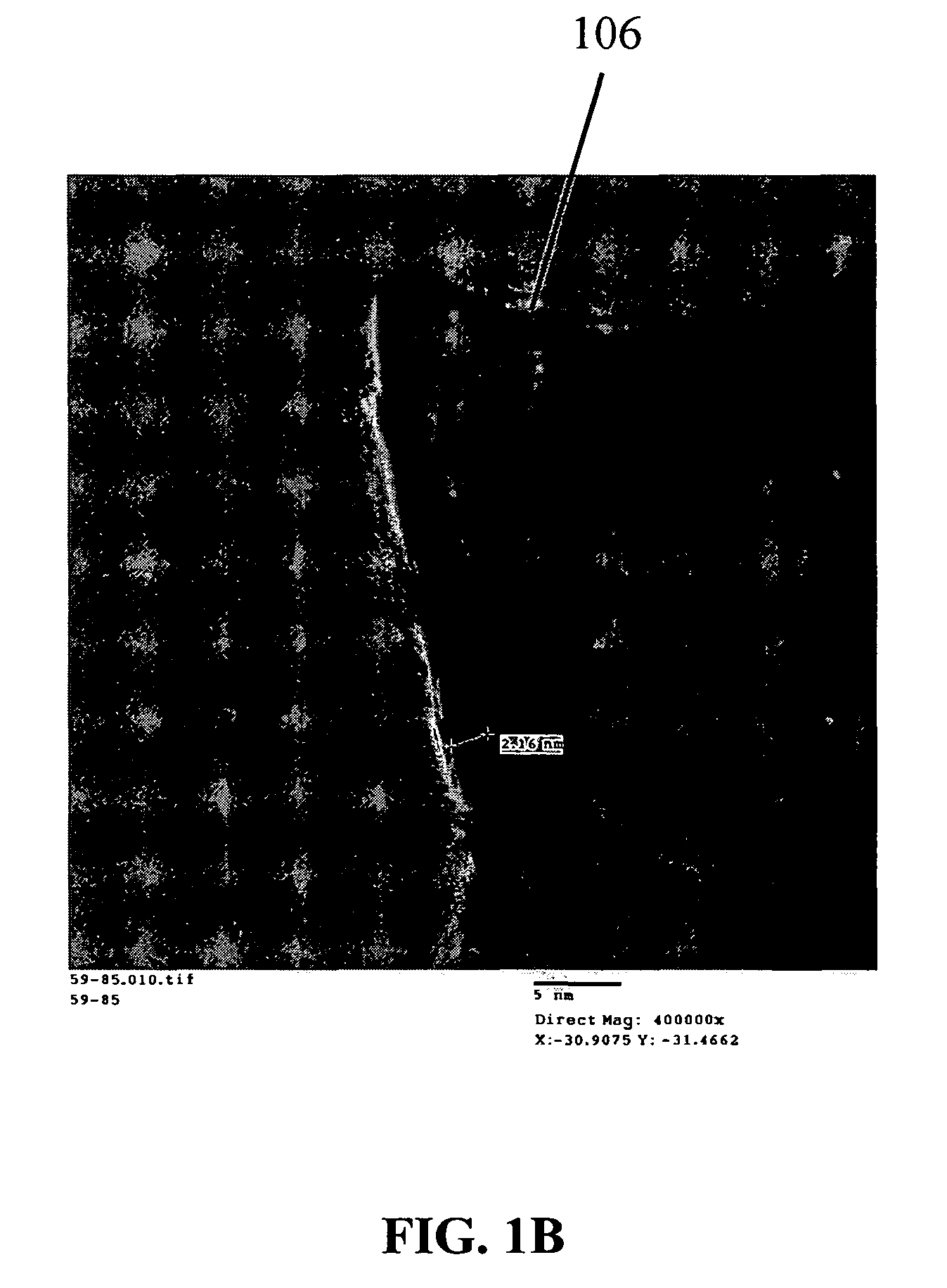
[0209]Silicon nanowires coated with WO3 were heated at 650° C. for 30 minutes, followed by 1250° C. for 6 min in the presence of a flowing gas mixture comprising Ar (430 cc / min), H2 (130 cc / min) and CH4 in Ar (228 cc / min). After the preparation was cooled, an interconnected nanowire network 300 comprising interconnected nanowire structures 100 was formed. The nanowire structures 100 comprising Si nanowire cores 102, carbon based layers 104 (SiC / WC interfacial carbide layers) and carbon-based structures 106 (graphene nanographitic plates) connecting the nanowire structures 100.

example 2

Deposition of Nanoparticles on Nanowires

[0210]Approximately 10 mg Si nanowires were dispersed in ethanol by sonication to form a nanowire suspension. An interconnected nanowire network was prepared by vacuum filtration of the nanowire suspension over a polyvinylidene fluoride (PVDF) membrane and vacuum drying, then 2 cc 0.1% polylysine solution was added to the filter funnel to absorb polylysine on the surface of the nanowires. After 5 minutes, all liquid in the funnel was vacuum removed and the nanowire network was separated from the PVDF membrane. After being dried in an oven at 100° Celsius for 15 minutes, the nanowire network was submerged in 10 cc of Au colloid solution (10 nm colloids) and soaked for 20 minutes to absorb the Au nanoparticles on the surface of the nanowires. Finally, the nanowire network was removed from the Au colloid solution, rinsed with isopropyl alcohol (IPA), and dried at 100° Celsius to obtain a nanowire network coated with gold nanoparticles. FIG. 14 sh...

example 3

Fabrication of Densely Packed Nanowires

[0211]In order to examine methods to increase packing density of nanowires, “bird's-nest” structures of 60 nm silicon nanowires were prepared using various techniques. The results of the methods are represented below in Table 1:

[0212]

TABLE 1Packing Density RelativeMethodto Silicon DensityAs collected on the filter  6%Stirred with shear mixer 6.1%Uniaxially pressed11.2%Surfactant (Triton X-100)  8%Die pressed, 40 KPSI46.6%Compact Packing (90°)78.5%Compact Packing (0°)90.7%

[0213]The packing density prepared by filtering the dispersion of 60 nm nanowires was 6%. Stirring the dispersion with a high speed shear mixer prior to filtration did not improve the packing density. A packing density increase of more than 30% was noted by adding surfactant (Triton X-100) to the nanowire dispersion prior to filtration. A significant increase in packing density was observed after application of uniaxial pressure to the nanowires. A packing density of 46.6% was ...


PUM

PropertyMeasurementUnit
thicknessaaaaaaaaaa
temperatureaaaaaaaaaa

Abstract

The present invention is directed to nanowire structures and interconnected nanowire networks comprising such structures, as well as methods for their production. The nanowire structures comprise a nanowire core, a carbon-based layer, and in additional embodiments, carbon-based structures such as nanographitic plates consisting of graphenes formed on the nanowire cores, interconnecting the nanowire structures in the networks. The networks are porous structures that can be formed into membranes or particles. The nanowire structures and the networks formed using them are useful in catalyst and electrode applications, including fuel cells, as well as field emission devices, support substrates and chromatographic applications.

Description

CROSS REFERENCE TO RELATED APPLICATIONS[0001]The present application is a continuation-in-part of U.S. patent application Ser. No. 11 / 295,133, filed Dec. 6, 2005, now U.S. Pat. No. 7,179,561, which claims the benefit of U.S. Provisional Patent Application Nos. 60 / 634,472, filed Dec. 9, 2004, and 60 / 738,100, filed Nov. 21, 2005. The present application also claims the benefit of U.S. Provisional Patent Application No. 60 / 801,377, filed May 19, 2006, and U.S. Provisional Patent Application No. 60 / 738,100, filed Nov. 21, 2005. The disclosures of each of these applications are incorporated herein by reference in their entireties.BACKGROUND OF THE INVENTION[0002]1. Field of the Invention[0003]The present invention relates to various nanowire structures, and to interconnected nanowire networks comprising such structures. The present invention also relates to the use of these nanowire structures and interconnected nanowire networks in fuel cells, as field emitting elements and other applic...

Claims


Application Information

Patent Timeline
Patent Type & Authority Patents(United States)
IPC IPC(8): H01M4/96C01B31/00B05D5/12H01M4/02H01M4/133
CPCH01B1/04H01M4/8605H01M8/1004H01M8/1097H01M4/8657H01M4/133H01M4/625Y02E60/521Y10T428/2918Y02P70/50Y02E60/50Y02E60/10
Inventor NIU, CHUNMING
Owner ONED MATERIAL INC
Why Eureka
Try Eureka