Reference current generator circuit for low-voltage applications

a reference current generator and low-voltage technology, applied in the direction of electric variable regulation, process and machine control, instruments, etc., can solve the problems of voltage vdd and the whole circuit cannot operate normally, so as to improve the phase margin of the reference current generator circuit, reduce the application condition of operation voltage, and improve the effect of phase margin

Active Publication Date: 2011-05-17
FARADAY TECH CORP
View PDF9 Cites 8 Cited by
  • Summary
  • Abstract
  • Description
  • Claims
  • Application Information

AI Technical Summary

Benefits of technology

[0010]In the aforementioned reference current generator circuit, layers of transistors are relatively less, which avails to reduce an application condition of the operation voltage. The capacitor compensation and the resistor compensation can improve a phase margin of the reference current generator circuit, so as to achieve a stable loop. Due to the resistance compensation provided by the compensation circuit, only a moderate capacitance compensation is required to enhance the phase margin. Therefore, in low-voltage applications, applying of a bulk capacitor is unnecessary, and the chip area and cost of the reference current generator circuit can be reduced.
[0011]In an embodiment of the present invention, the compensation circuit includes two current mirrors, and the reference current generator circuit further includes another current mirror. Based on coupling relation of the current mirrors and a current reproducing characteristic of the current mirrors, the compensation circuit can reproduce the reference current generated by the external resistor, so as to eliminate the effect on currents caused by the parallel coupling of the equivalent resistance and the external resistor.

Problems solved by technology

However, when an operation voltage VDD of the reference current generator circuit is excessively low, limited by the structure of the circuit and the fabrication process of the MOSFET, headroom available to the MOSFETs M1 and M2 are insufficient, so that the whole circuit cannot operate normally.

Method used


Image

  • Reference current generator circuit for low-voltage applications
  • Reference current generator circuit for low-voltage applications
  • Reference current generator circuit for low-voltage applications

Examples


Embodiment Construction

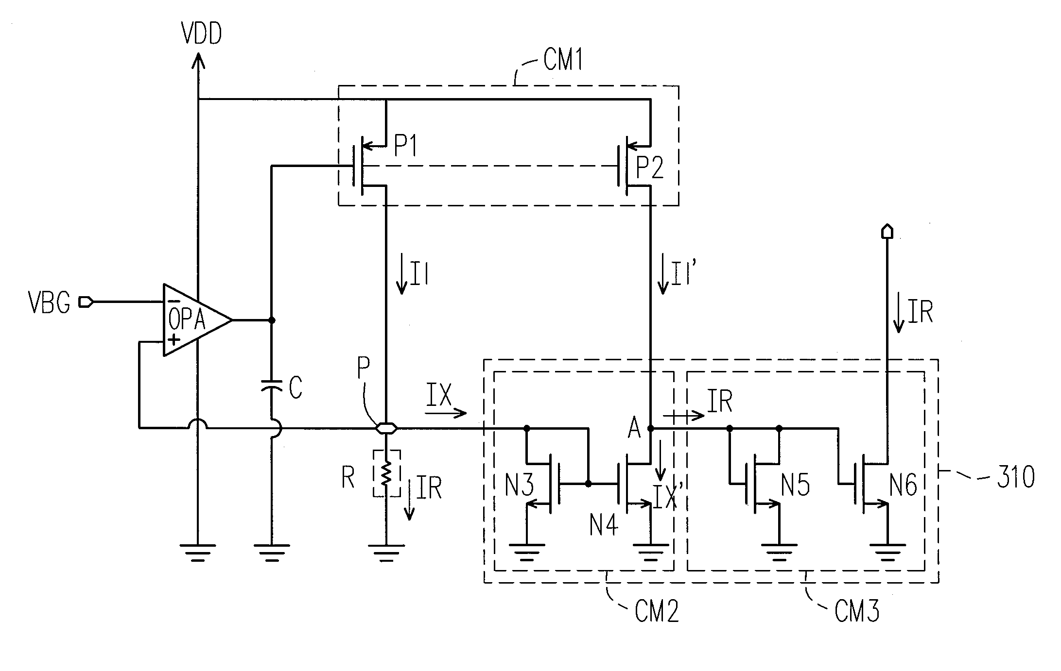
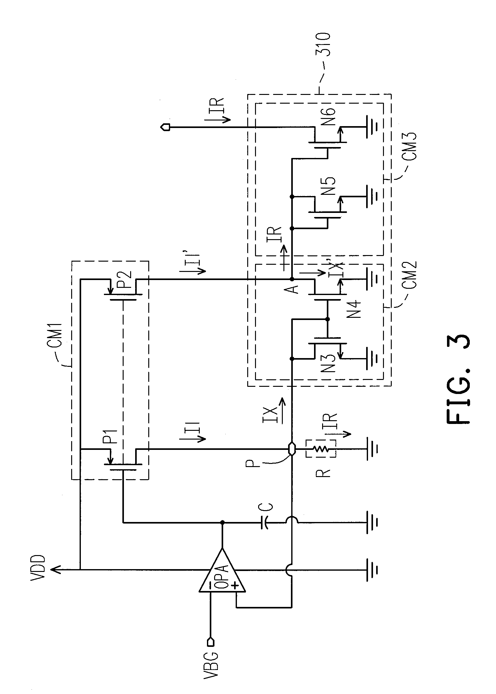
[0016]FIG. 3 is a schematic diagram illustrating a reference current generator circuit for low-voltage applications according to an embodiment of the present invention. Referring to FIG. 3, the reference current generator circuit of FIG. 3 includes an operational amplifier OPA, a capacitor C, an external resistor R, a current mirror CM1 and a compensation circuit 310. Wherein, the compensation circuit 310 includes current mirrors CM2 and CM3. Most of components of the reference current generator circuit are disposed within a chip, and the external resistor R and a ground terminal thereof is located outside the chip, and other components of the circuit are all within the chip. The pad P is a circuit connection point for connecting internal and external of the chip.

[0017]An inverting input terminal of the operational amplifier OPA receives a reference voltage VBG from a bandgap reference circuit, and a non-inverting input terminal of the operational amplifier OPA is coupled to the chi...


PUM


Abstract

A reference current generator circuit suitable for low-voltage applications is provided. The generator circuit is fabricated in a chip for generating a precise reference current based on a precise reference voltage and a precise external resistor. The generator circuit provides an equivalent resistance coupled in parallel with the external resistor to provide resistance compensation and reduce the impedance of seeing into the chip from a chip pad. In addition to the resistance compensation, only moderate capacitance compensation is required to enhance the phase margin of the generator circuit, so as to achieve a stable loop. Therefore, chip area and cost can be reduced in low-voltage applications. In addition, the generator circuit reproduces the reference current generated by the external resistor by utilizing current mirrors, so as to eliminate the effect on currents caused by parallel coupling of the equivalent resistance and the external resistor.

Description

CROSS-REFERENCE TO RELATED APPLICATION[0001]This application claims the priority benefit of Taiwan application serial no. 97133630, filed on Sep. 2, 2008. The entirety of the above-mentioned patent application is hereby incorporated by reference herein and made a part of specification.BACKGROUND OF THE INVENTION[0002]1. Field of the Invention[0003]The present invention relates to a reference current generator circuit for low-voltage applications. More particularly, the present invention relates to a reference current generator circuit applying resistance compensation for increasing phase margins.[0004]2. Description of Related Art[0005]FIG. 1 is a diagram illustrating a conventional reference current generator circuit applying a N-channel metal-oxide-semiconductor field effect transistor (NMOSFET) as a second stage of an operational amplifier. All of components illustrated in the circuit of FIG. 1 are within a chip besides an external resistor R and a ground terminal connected to th...

Claims


Application Information

Patent Timeline
Patent Type & Authority Patents(United States)
IPC IPC(8): G05F3/16
CPCG05F3/262G05F1/561
Inventor HUANG, TING-CHUNCHEN, KUAN-YUCHANG, YUAN-HSUN
Owner FARADAY TECH CORP
Why Eureka
Try Eureka