Transient RF detector and recorder

a transient rf detector and recorder technology, applied in the direction of transmission monitoring, receiver monitoring, instruments, etc., can solve the problems of irreversible damage to a wide range of electrical and electronic equipment, including computers and radio or radar receivers, equipment can be irreversibly damaged or, in effect, electrically destroyed, and complete replacement of equipmen

Inactive Publication Date: 2011-05-17
HPM SECURITY ASSOC
View PDF5 Cites 12 Cited by
  • Summary
  • Abstract
  • Description
  • Claims
  • Application Information

AI Technical Summary

Benefits of technology

[0020]Typical HPM and TED threat sources are expected to generate significant signal energy over a range from hundreds of MHz to multiple GHz in frequency. This implies the need for antenna structures that exhibit relatively flat amplitude-bandwidth response over a decade or more in frequency. Conical monopole structures working against a ground plane have been shown in literature and practice to exhibit such wideband response. A somewhat similar response is possible in a planar structure in the form of a triangular shape monopole element working against a ground plane. The planar arrangement is easier to manufacture in the form of a printed circuit board (PCB) versus a three-dimensional metallic structure, such as a conic shape. A significant challenge to the performance of wideband antennae is encountered in the conventional approach of first optimally matching the antenna source impedance to a transmission line which is used to convey the received signals to a remotely-located detector. The antenna impedance typically varies greatly over the frequency range of interest making the wideband impedance matching difficult. This difficulty can be mitigated for the case of simple envelope detection by incorporating the envelope detector into the antenna structure with no intervening transmission line. Here, the envelope detector signal output is applied to an amplifier having high-input impedance to avoid significant loading of the detector elements. The amplified signal output is then available for further signal processing.
[0022]This example antenna / detector element has the feature of simple combining of multiple elements to recover the peak detected level of two or three (or more) elements. This is possible by simple parallel connection of the detector outputs at the high-impedance amplifier input since the individual detector outputs are diodes. The rectified signal of the antenna / detector element receiving the highest RF signal is passed on to the high-impedance amplifier without significant loading by the other antenna elements.
[0026]The directional-sensing wideband frequency detection device may include a fifth detector unit centrally situated along a third axis in a second plane, wherein the third axis is perpendicular to the first and second axis and intersects the first and second axis at the point of intersection of the first and second axis, wherein the point of intersection of the first and second axis is substantially equidistant from the first, second, third, fourth, and fifth detector units. Furthermore, the directional-sensing wideband frequency detection device may also include a sixth detector unit centrally situated along the third axis in the second plane, wherein the point of intersection of the first and second axis is substantially equidistant from the first, second, third, fourth, fifth, and sixth detector units. The fifth and sixth detector units may provide a vector in a third dimension in order to facilitate resolution of directional finding bearings in three dimensions (e.g., azimuth angle and elevation angle).
[0032]In many conventional DF systems, sector antenna outputs are coupled via RF transmission lines to receive electronics for processing. Prior art sector antennae are relatively limited in the following desirable simultaneous properties: sensitivity to signals over a wide frequency range and wide range of signal polarization orientations and relatively uniform beam width over that frequency range and the ability to efficiently couple the signals to a transmission line to convey to signal processing electronics equipment. The present DF system invention achieves the aforementioned bandwidth, beam width and arbitrary polarization sensitivity properties by incorporating diode envelope detectors within each sector antenna / detector unit. This design relieves the requirement to efficiently couple the recovered RF signals to a transmission line to convey to processing electronics. In this design, only the detected (baseband) envelope information of the detected RF signal is conveyed to the processing electronics. Accordingly, the DF sector antenna / detector units include monopole / detector elements that are co-planar but at angles to each other in their common plane. In an exemplary embodiment, four monopole / detector elements oriented in increments of 90 degrees within their common plane may be used to form the basis of each sector antenna / detector unit. However, the present invention may alternatively employ only three monopole / detector elements oriented at 120 degrees to each other in their common plane within each sector antenna / detector unit and still achieve the desired sensitivity to signals of arbitrary polarization orientation. The co-planar monopole / detectors are parallel-connected so that sensitivity to signals arriving approximately normal (+ / − at least 45 degrees) to their common plane is achieved regardless of the polarization orientation of the incoming wave. Wideband directional properties are introduced to the sector antenna / detector unit by placing RF absorber material behind the plane of the monopole / detector elements. The absorber material is backed by metallic foil which also extends up the sides of the absorber. The relative size of the absorber material and the distance of metallic coverage up the sides are selected to adjust the sector beam-width to approximately 90 degrees.
[0034]The present invention also includes an RF generator to field verify that any of the aforementioned detector systems continue to function following some stressful event (e.g., the device is dropped onto a concrete floor). A piezoelectric spark generator creates a broadband RF spectrum which is applied to an antenna structure which radiates the signal with frequency response, directivity and polarization determined by the antenna structure. Generally, a piezoelectric spark generator is mounted in place of the RF probe that would normally launch RF signals from a coaxial transmission line into a rectangular waveguide. Use of an open rectangular waveguide provides a source for an efficient, directional, linearly polarized emission.

Problems solved by technology

The result may be irreversible damage to a wide range of electrical and electronic equipment, particularly computers and radio or radar receivers.
Subject to the electromagnetic hardness of the electronic equipment, a measure of the equipment's resilience to this effect, and the intensity of the field produced by an EMP emission, the equipment can be irreversibly damaged or, in effect, electrically destroyed.
The damage inflicted is not unlike that experienced through exposure to close proximity lightning strikes, and may require complete replacement of the equipment, or at least substantial portions thereof.
Commercial computer equipment is particularly vulnerable to EMP effects, as it is largely built up of high-density Metal Oxide Semiconductor (MOS) devices, which are very sensitive to exposure to high voltage transients.
Even if the pulse is not powerful enough to produce thermal damage, the power supply in the equipment will readily supply enough energy to complete the destructive process.
Affected devices may still function, but their reliability will be seriously impaired.
For example, the circuitry may be undamaged but data corruption has occurred.
Shielding electronics by equipment chassis provides only limited protection, as any cables running in and out of the equipment will behave very much like antennae, in effect guiding the high-voltage transients into the equipment.
Computers used in data processing systems, communications systems, displays, industrial control applications, including road and rail signaling, and those embedded in military equipment, such as signal processors, electronic flight controls and digital engine control systems, are all potentially vulnerable to the EMP effect.
Other electronic devices and electrical equipment may also be destroyed by the EMP effect.
Telecommunications equipment can be highly vulnerable, due to the presence of lengthy copper cables between devices.
Receivers of all varieties are particularly sensitive to EMP, as the highly-sensitive miniature high-frequency transistors and diodes in such equipment are easily destroyed by exposure to high-voltage electrical transients.
Therefore radar and electronic warfare equipment, satellite, microwave, UHF, VHF, HF and low band communications equipment and television equipment are all potentially vulnerable to the EMP effect.
However, current RF detection devices of various designs either suffer from false positive alerts due to their sensitivity to local static discharge, or are relatively insensitive to transient electromagnetic pulse signals and RF signals of very short pulse duration.
Current RF direction-finding (DF) devices also suffer from poor sensitivity and poor bearing resolution for transient electromagnetic pulse signals and RF signals of very short pulse duration.
Current antennas used in RF-DF devices have either sensitivity limited to signals over a relatively narrow range of frequencies or sensitivity over a relatively limited range of signal polarization orientations.

Method used


Image

  • Transient RF detector and recorder
  • Transient RF detector and recorder
  • Transient RF detector and recorder

Examples


Embodiment Construction

[0043]For purposes of the description hereinafter, spatial or directional terms shall relate to the invention as it is oriented in the drawing figures. However, it is to be understood that the present invention may assume various alternative variations, except where expressly specified to the contrary. It is also to be understood that the specific apparatus illustrated in the attached drawings, and described in the following specification, is simply an exemplary embodiment of the invention. Hence, specific dimensions and other physical characteristics related to the embodiments disclosed herein are not to be considered as limiting, unless otherwise indicated. The present invention will now be described with reference to the accompanying figures.

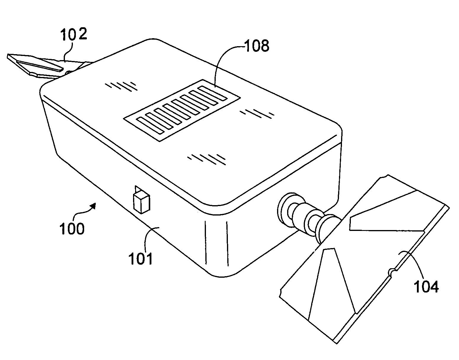
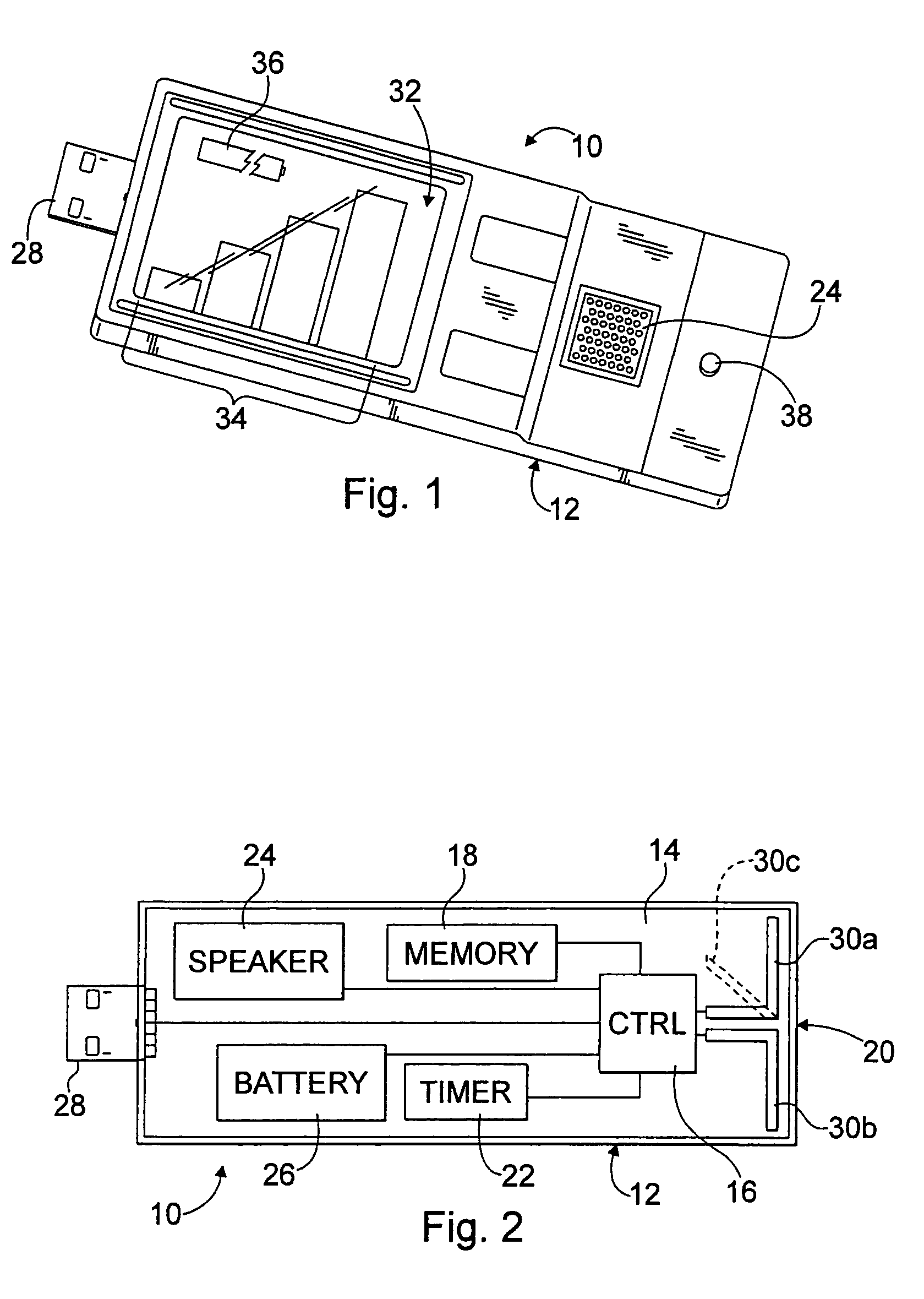
[0044]With reference to FIGS. 1 and 2, a device 10 for detecting a predefined RF transmission of electromagnetic radiation is shown. In a desirable embodiment, the device 10 includes a housing 12 having a circuit board 14 containing or connec...


PUM


Abstract

A portable device for detecting a radio frequency transmission of electromagnetic radiation includes a housing; a controller situated within the housing; memory communicatively connected to the controller; an antenna connected to the controller and configured to receive the radio frequency transmission; and an audio-generating component connected to the controller. The radio frequency transmission of the electromagnetic radiation is harmful to an electrical device and is from a transient electromagnetic device (TED) threat source. The controller is operative for sensing magnitude, duration, and / or repetition of the radio frequency transmission; identifying a class of the radio frequency transmission based on one of the magnitude, duration, and repetition associated with the radio frequency transmission; and causing the audio-generating component to output tones to provide aural discrimination of an identified class of the radio frequency transmission received by the portable device. The identified class is a transient electromagnetic pulse signal from the TED source.

Description

CROSS REFERENCE TO RELATED APPLICATIONS[0001]This application claims the benefit of U.S. Provisional Patent Application No. 60 / 810,046, filed Jun. 1, 2006, and entitled “Transient RF Detector and Recorder,” the contents of which are incorporated herein by reference.BACKGROUND OF THE INVENTION[0002]1. Field of the Invention[0003]The present invention relates generally to detection of electromagnetic radiation that may be harmful to a user or electrical device and, more specifically, to a device for detecting the magnitude, duration, repetition, and emission direction of the electromagnetic radiation and informing the user of same.[0004]2. Description of Related Art[0005]The electromagnetic pulse (EMP) effect was first observed during the early testing of high altitude airburst nuclear weapons. The effect is characterized by the production of a very short (e.g., hundreds of nanoseconds) but intense electromagnetic pulse, which propagates away from its source with ever diminishing inte...

Claims


Application Information

Patent Timeline
Patent Type & Authority Patents(United States)
IPC IPC(8): H04B17/00
CPCG01R29/0814H04B17/23G01R29/0892G01R29/0871
Inventor SULKOWSKI, JR., ROBERT V.ZBOROWSKI, RONALD W.
Owner HPM SECURITY ASSOC
Why Eureka
Try Eureka