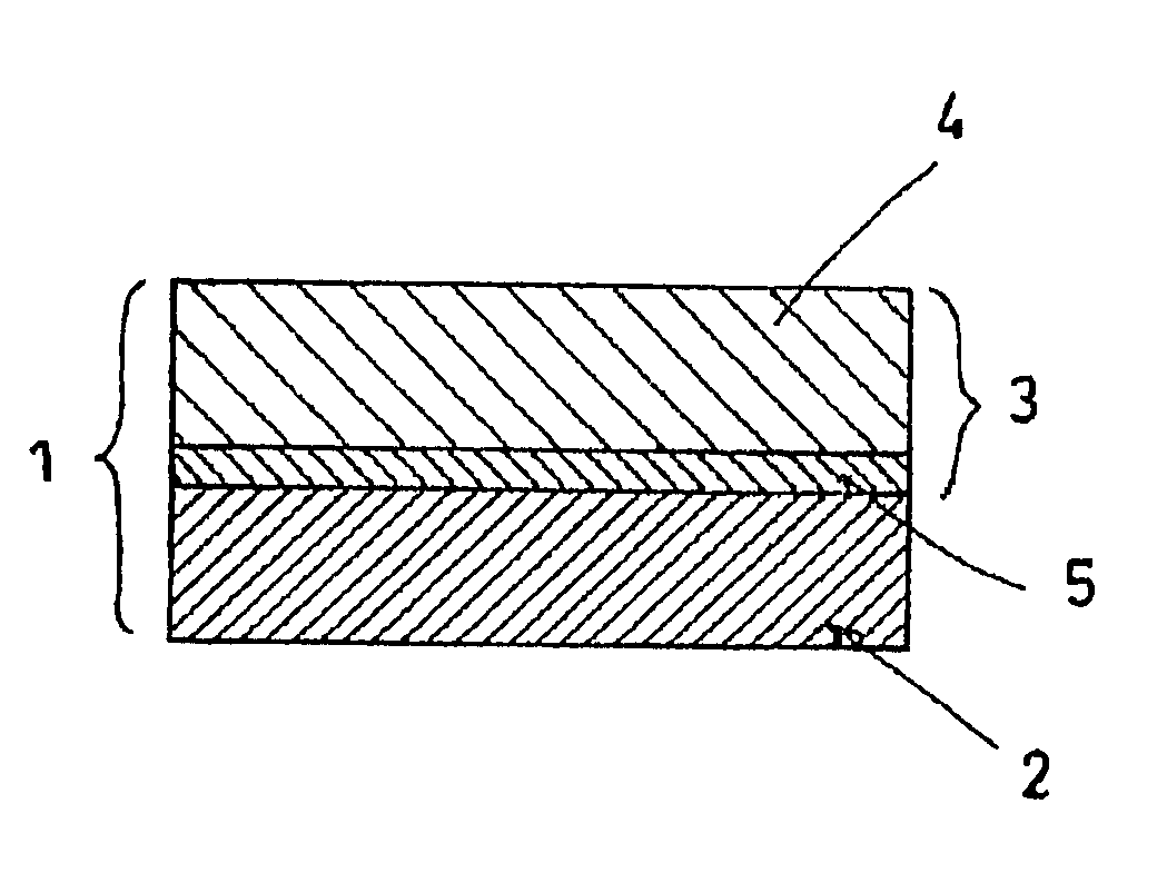
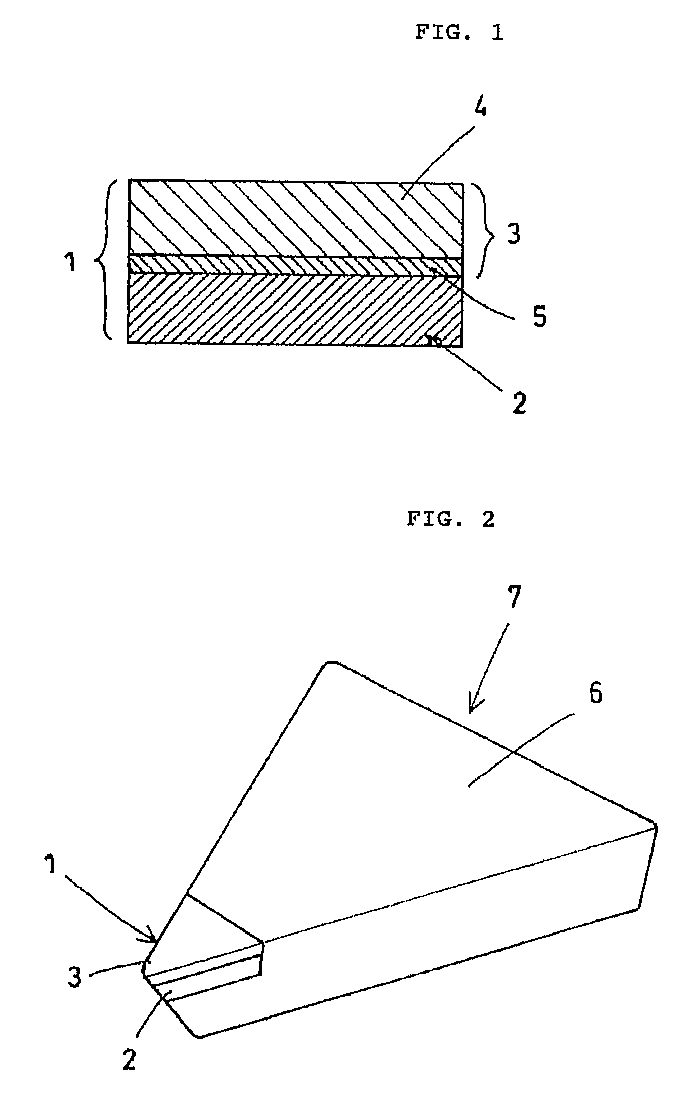
Diamond sintered compact
a diamond sintered compact and compact technology, applied in the field of high wear resistance, high chipping resistance diamond sintered compact, can solve the problems of easy abnormal grain growth of diamond grains, devising improvements, and limiting the effort to improve the properties of diamond sintered compacts, so as to improve the wear resistance, and improve the effect of wear resistan
- Summary
- Abstract
- Description
- Claims
- Application Information
AI Technical Summary
Benefits of technology
Problems solved by technology
Method used
Image

Examples
example 1
[0064]Diamond sintered compacts designated as sample nos. 11 to 20 were produced using cemented carbide substrates with the compositions shown in Table 1. The residual compressive stress in the main diamond layer was measured. Also measured was the amount of cutting tool flank wear when the obtained diamond sintered compact was used as the cutting edge in a cutting tool.
[0065]The diamond sintered compacts were specifically produced as follows. Diamond grains (diamond powder) with an average grain size of 5 μm and binder (Co powder) were first dry mixed in a mixing proportion of 80 weight % diamond grains and 20 weight % Co powder. The binder used for sample no. 16 was a mixture of 16 weight % Co powder and 4 weight % titanium powder, while the binder used for sample no. 17 was a mixture of 12 weight % Co powder and 8 weight % titanium powder.
[0066]The diamond grain and binder starting mixture was filled into a tantalum container so as to come into contact with a substrate (disk); th...
example 2
[0078]Diamond sintered compacts designated as sample nos. 21 to 28 were fabricated using the ratios shown in Table 2 for the mixing quantities of the diamond powder and Co powder made into a paste for coating on the cemented carbide substrate. For purposes of comparison, the diamond sintered compact designated as sample no. 29 was fabricated without the application of the paste mixture of diamond powder and Co powder. The following were measured on the obtained diamond sintered compacts: the residual compressive stress, the difference between the Co content of the main diamond layer and the Co content of the Co-rich diamond layer, the thickness of the Co-rich diamond layer, and the amount of cutting tool flank wear when the diamond sintered compact was employed as the cutting edge of a cutting tool.
[0079]The diamond sintered compacts in sample nos. 21 to 28 were produced in this example using the same fabrication method and fabrication conditions as in Example 1, while using a subst...
example 3
[0087]Diamond sintered compacts, designated as sample nos. 31 to 34, were fabricated in which the main diamond layer contained diamond grains having the diamond grain size shown in Table 3. The amount of cutting tool flank wear was measured for application of the obtained diamond sintered compacts as the cutting edge of a cutting tool. The diamond content and transverse rupture strength of the obtained diamond sintered compacts was also measured.
[0088]The diamond sintered compacts were fabricated by filling the starting material, comprising a mixture of diamond grains and binder (Co—W—Ti alloy (Co: 80 wt %, W: 5 wt %, Ti: 5 wt %), into a tantalum container so as to be in contact with a cemented carbide substrate (disk) having a composition of WC-10% Co. In order to prepare a diamond sintered compact having a Co-rich diamond layer, a heat treatment was carried out for 10 minutes at 1300° C. in a (CO+CO2) reducing atmosphere having a CO concentration of 4% in order to induce the depos...
PUM
| Property | Measurement | Unit |
|---|---|---|
| residual compressive stress | aaaaa | aaaaa |
| thickness | aaaaa | aaaaa |
| thickness | aaaaa | aaaaa |
Abstract
Description
Claims
Application Information