Continuous high shear mixing process

a high shear and mixing technology, applied in the direction of process and machine control, transportation and packaging, instruments, etc., can solve the problems of high cost of conventional homogenizers, large amount of horsepower, and inability to use batch type shear mixers in most cases, so as to achieve energy saving and reduce capital costs

Active Publication Date: 2011-11-01
LOPRESTI WILLIAM J
View PDF11 Cites 16 Cited by
  • Summary
  • Abstract
  • Description
  • Claims
  • Application Information

AI Technical Summary

Benefits of technology

[0028]In addition to particle size reduction and viscosity applications, dry solids incorporation is aided by mixing with predetermined residence times. Oil based flavor additives injected into juice streams benefit by employing predictable and adequate residence times to ensure two phase emulsions. Where multiple stage homogenizations are required to achieve a specific size emulsion, shear mixing with residence time makes single stage homogenization viable.
[0029]The present invention allows replacement of conventional homogenization with lower capital costs and energy savings.

Problems solved by technology

1. Reduction of viscosity of orange and grapefruit juices in a taste evaporator while minimizing insoluble imperfections. Current technology uses high-pressure piston style homogenizers placed within the evaporator between stages.
2. Reduction of particle size of pulp and / or fiber in orange and grapefruit juices, as well as a wide variety of concentrate bases and purees. The reduction is normally required for improved appearance and mouth feel. Current technology uses high-pressure piston style homogenizers placed after juice extraction and finishing.
3. Reduction of particle size of pulp in concentrate bases and single strength juices for permitting these products to be heated and / or cooled in a plate type heat exchanger. The plate type heat exchangers are restricted to products containing specifically sized particles.
4. Creation of stable oil / aqueous phase emulsion in blending citrus oils and other flavors as ingredients into a blended recipe. Flavor and minor component ingredient incorporation into blends are often problematic unless high-pressure homogenization is used. Many smaller companies accept a lesser quality product because of the high capital and maintenance costs of the equipment.
The conventional homogenizer is expensive and consumes large amounts of horsepower because the required discharge may be in the approximately 2500 to 5000 psi range.
The use of batch type shear mixers is not practical in most cases because processes must be continuous flow.
Replacing the homogenizer with an inline mechanical high shear pumping device is also not usually viable.
Although mechanical shearing may be an alternative to the much higher shear homogenizing device, it requires much greater residence times. The inline mixer, even with multiple staging, cannot control the residence time.
While batch mechanical shear mixing and homogenization are easily scaled up from lab tests, it is difficult to predict the results achieved when the scale up involves inline mechanical shear mixing using a shear pumping device.
These same problems extend to the production of chemical solutions, micron-scale polymer beads, emulsions, suspensions, and other products that require blending, homogenizing, solubilizing, dispersion, or reduction of particle size.

Method used


Image

  • Continuous high shear mixing process
  • Continuous high shear mixing process
  • Continuous high shear mixing process

Examples


embodiment 11

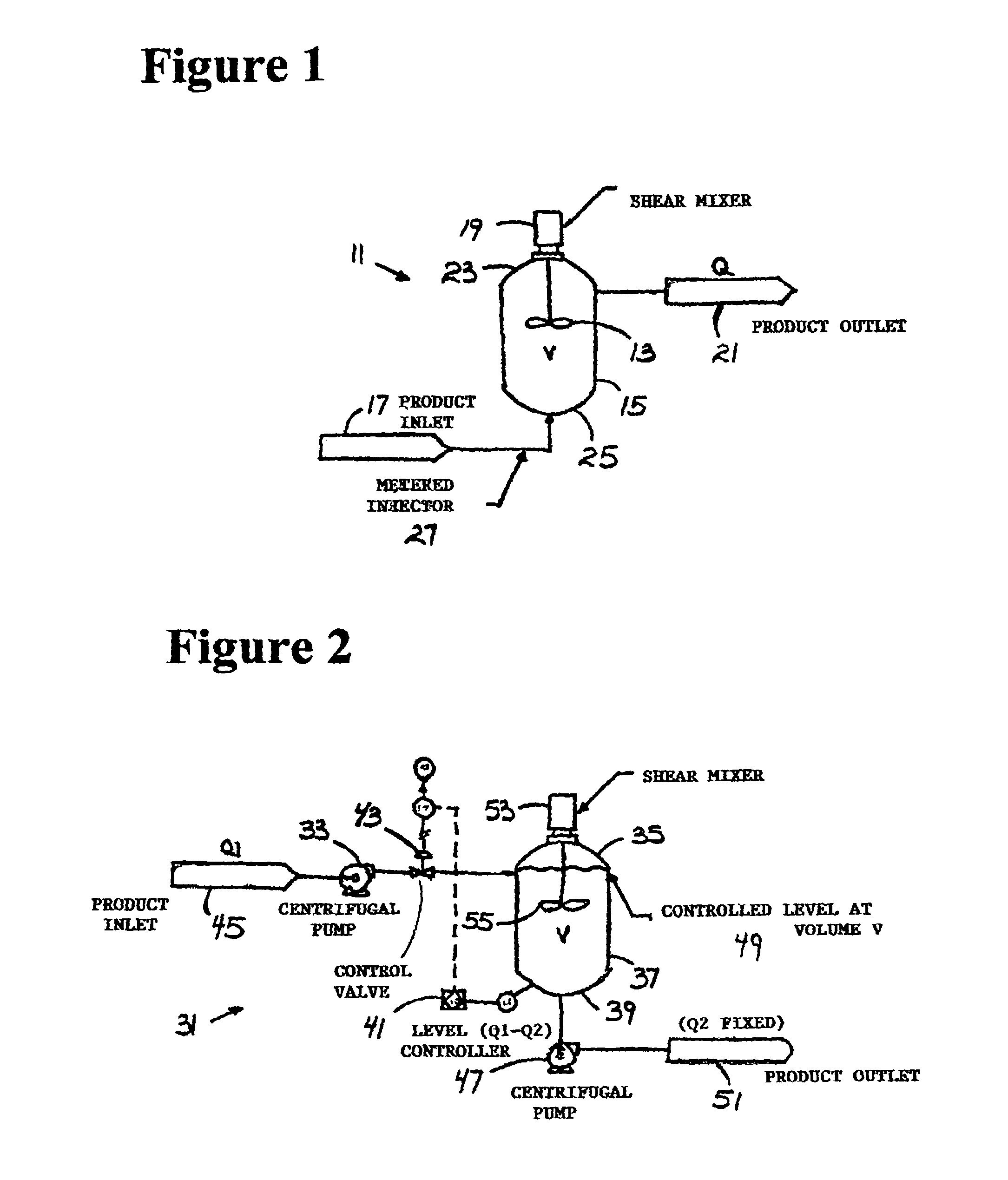
[0038]FIG. 1 is a schematic diagram of a constant flow embodiment 11 for an apparatus for preparing juice or beverages or any other product that requires homogenization, reduction of particle size, blending, solubilizing, dispersion, suspension, or emulsification. The vessel 11 is sized for the maximum needed residence time and is preferably open to atmosphere. The mixing chamber incorporates a batch shear mixer 13 in a tank 15 with a pressure seal that allows continuous flow. The device includes a product inlet 17, a holding tank 15 connected to the product inlet 17, a product shear mixer 13 mounted in the holding tank 15, a motor 19 connected to the shear mixer 13 for rotating the shear mixer 13 in the holding tank 15, and a product outlet 21 connected to the holding tank 15 for continuously and constantly flowing the product from the holding tank 15. The holding tank has a top 23 and a bottom 25 and the product inlet 17 is connected near a bottom 25 of the holding tank 15 and the...

embodiment 31

[0040]FIG. 2 is a schematic diagram of a variable flow embodiment 31 for low viscosity. Pumps 33 pump into a top 35 of a mixing chamber 37 and flow exits a bottom 39 of the tank 37. The device 31 is used with various products and / or variable flow rates. The vessel 31 is sized for the maximum needed residence time and is preferably open to atmosphere. The mixing chamber 37 incorporates a motor 53 connected to a batch shear mixer 55 in a tank 37. A level controller 41 controls a valve 43 or a positive displacement pump at the inlet 45. Systems are designed for use with various products and flow rates by sizing the mixing chamber 37 for the maximum needed residence time, opening the vessel to the atmosphere and installing a level monitor 41 in the tank 37. The volume, determined by the level, serves as a controlled process variable for residence time control. A variable speed extraction pump 47 controls the level on a closed loop control. When the incoming flow rate matches the outgoin...

embodiment 61

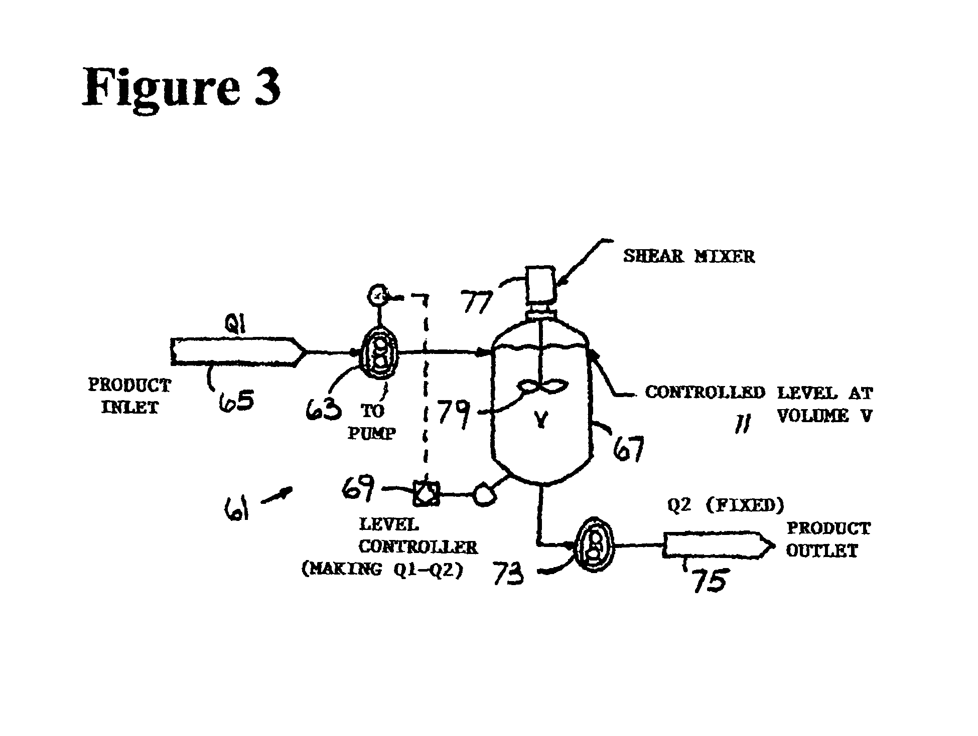
[0042]FIG. 3 is a schematic diagram of a variable flow embodiment 61 for high viscosity. This embodiment adds to the basic device a positive displacement pump 63 connected between a product inlet 65 and a holding tank 67, a level controller 69 connected to the holding tank 67 and connected to the inlet positive displacement pump 63 for controlling liquid level 71 in the holding tank 67, and an outlet positive displacement pump 73 connected between the holding tank 67 and a product outlet 75. A motor 77 controls a high shear mixer 79 in the holding tank

[0043]FIGS. 4, 5, and 6 show large hole, small hole, and slotted shearing heads 81, 83, 85 with central openings.

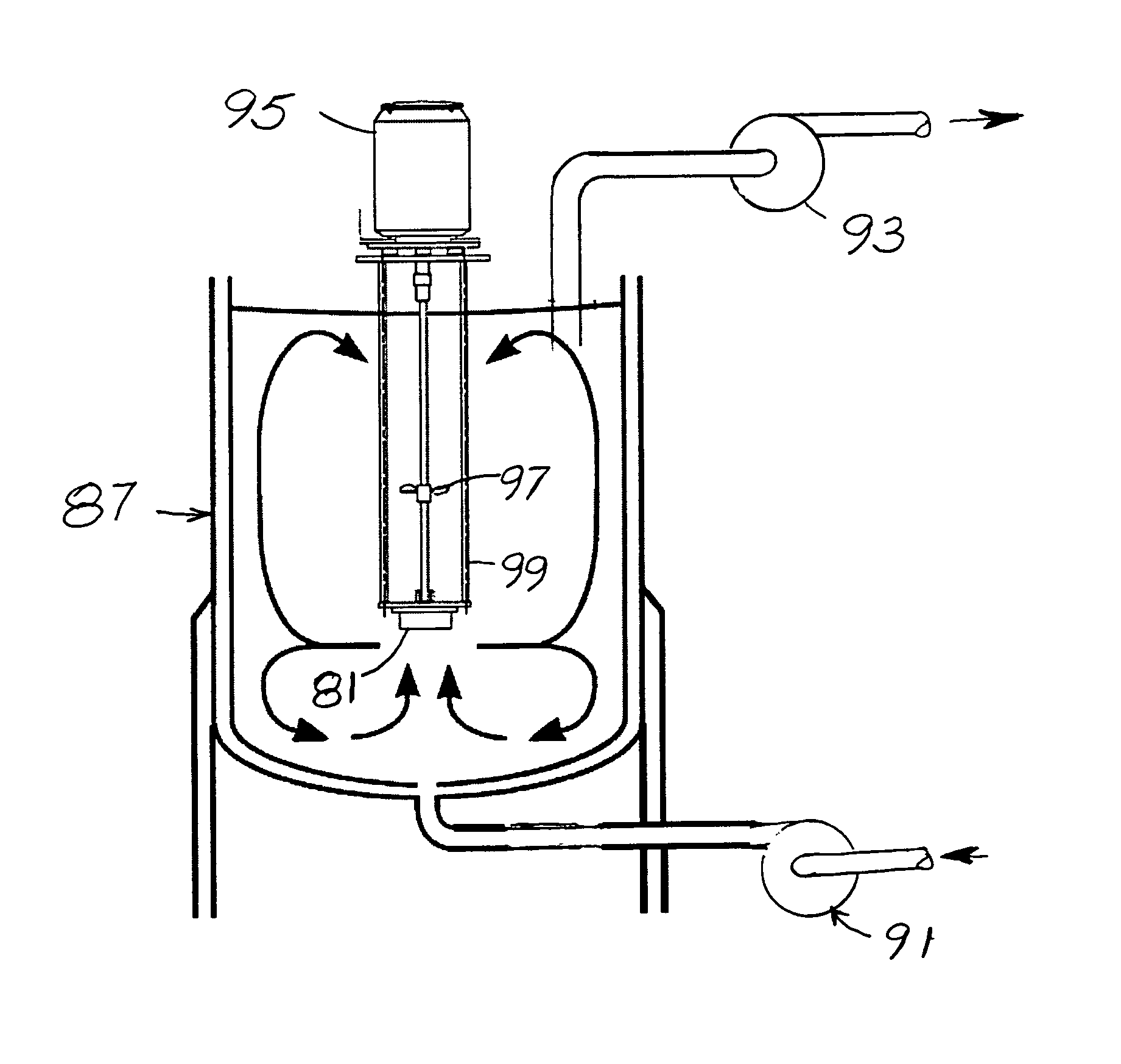
[0044]FIG. 7 shows an atmospheric residence tank 87 with coordinated inlet and outlet pumps 91, 93, shearhead motor 95, a shear mixer 97 in a screen 99 and a shearhead 81, 83, or 85.

[0045]The present invention also includes a method of providing juice or beverages or any other product that requires homogenization, reduction ...


PUM


Abstract

A high shear mixer in a holding tank is used in a continuous flow process. Flow rate of material into and out of the holding tank establishes residence time in contact with shearing elements. A batch shear mixer is used in a tank that has continuous flow into the bottom and out of the top. A level controller controls a valve or a positive displacement pump at the inlet. The mixing chamber is sized for the maximum needed residence time, slowing the flow increases the residence time. In an open tank lower inlet pump and upper outlet pump are coordinated. Incoming flow rate matches outgoing flow for continuous processing.

Description

[0001]This application claims the benefit of U.S. Provisional Application No. 60 / 687,329, filed Jun. 6, 2005, which is hereby incorporated by reference in its entirety.BACKGROUND OF THE INVENTION[0002]Many different types of concentrate bases and single strength juices are processed through a homogenizer to reduce pulpy fiber and make a uniform blend or puree. Pulpy juices are often homogenized to reduce particle size of the pulp and thus the apparent viscosity, such as “tight-end pulp” from a juice finisher.[0003]Juice processing often requires both homogenization and high shear to create juice concentrates, concentrate bases, and slurries. Homogenization and high shear are required to reduce viscosity, eliminate undesirable insoluble particles (imperfections), and reduce the size of pulp and other fibers that are present in single strength or concentrate juices. Typically, juice concentrates are shear thinning thixotropic liquids. Reducing the viscosity reduces pressure drops in p...

Claims


Application Information

Patent Timeline
Patent Type & Authority Patents(United States)
IPC IPC(8): B01F7/16
CPCB01F7/00641B01F7/00908B01F7/164B01F15/0035B01F2215/0014B01F27/192B01F27/50B01F27/812B01F35/2212B01F2101/06
Inventor LOPRESTI, WILLIAM J.
Owner LOPRESTI WILLIAM J
Why Eureka
Try Eureka