Sensing chip
a technology of sensing chip and sensor, which is applied in the field of photoelectron integration, can solve the problems of inability to adjust, low detection sensitivity, and inability to universalize and apply, and achieves the effects of high detection sensitivity, high precision, and reduced sample liquid
- Summary
- Abstract
- Description
- Claims
- Application Information
AI Technical Summary
Benefits of technology
Problems solved by technology
Method used
Image
Examples
example 1
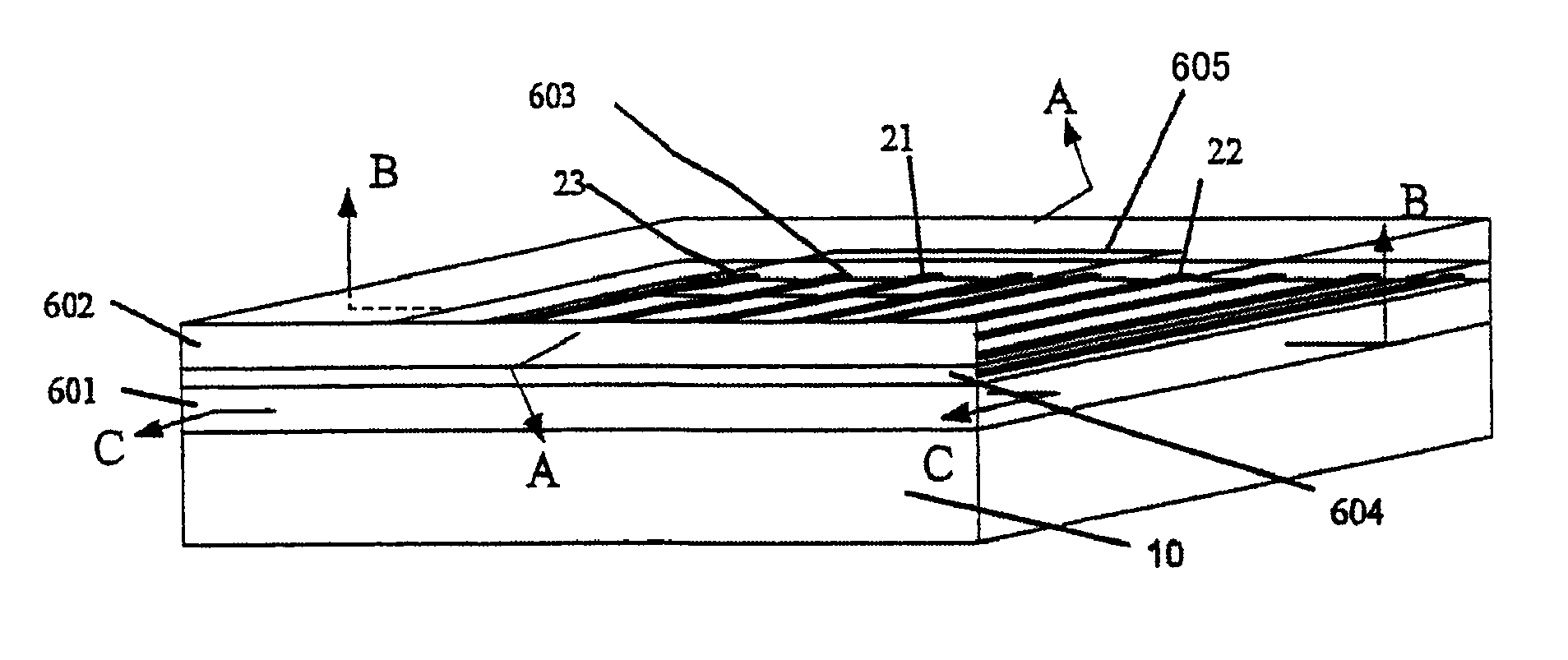
[0030]FIG. 6 is a diagram showing the basic structure of a sensing chip for a refractive index of a long-range surface plasmon polariton. FIG. 7 is an A-A sectional view of FIG. 6. FIG. 8 is a B-B sectional view of FIG. 6. FIG. 9 is a C-C sectional view of FIG. 6. An Si substrate (underlayer) 10 is selected. SiO2 or SiOx is selected as the material for a lower limiting layer 601 and an upper limiting layer 602, and lower limiting layer 601 is formed on Si substrate 10 by PECVD. A strip-like pattern of 81m in width is formed on lower limiting layer 601 by photolithography. Then, an Au thin film 603 of 20 nm in thickness is formed by sputtering or vapor deposition, and a measurement Au arm 21, a first reference Au arm 22 and a second reference Au arm 23 are formed by lifting or wet etching. Thereafter a buffer layer 604 made of SiOx or SiNy is formed by a method such as sputtering, vapor deposition or spin coater hardening. In response to specific measurement conditions, the thickness...
example 2
[0032]FIGS. 6, 7, 8 and 9 are diagrams showing the basic structure of Example 2 of a sensing chip of a long-range surface plasmon polariton for a refractive index. An Si substrate 10 is selected. SiO2 or SiOx (0≦x≦2) is selected as the material for a lower limiting layer 601 and an upper limiting layer 602, and lower limiting layer 601 is formed on Si substrate 10 by PECVD. A strip-like pattern of 8 μm in width is formed on lower limiting layer 601 by photolithography. Then, an Au thin film 603 of 20 nm in thickness is formed by sputtering or vapor deposition, and a measurement Au arm 21, a first reference Au arm 22 and a second reference Au arm 23 are formed by lifting or wet etching. Thereafter a buffer layer 604 made of SiOx or SiNy is formed by a method such as sputtering, vapor deposition or spin coater hardening.
[0033]In response to specific measurement conditions, the thickness of buffer layer 604 is set to 10 nm to 1 μm. Upper limiting layer 602 is formed by PECVD. Finally, ...
example 3
[0036]FIGS. 6, 7, 8 and 9 show the basic structure of Example 3 of a sensing chip for a refractive index of a long-range surface plasmon polariton. An Si substrate 10 is selected. BCB is selected as the material for a lower limiting layer 601 and an upper limiting layer 602, and lower limiting layer 601 is formed on Si substrate 10 by spin coater hardening. A strip-like pattern of 8 μm in width is formed on lower limiting layer 601 by photolithography. Then, an Au thin film 603 of 20 nm in thickness is formed by sputtering or vapor deposition, and a measurement Au arm 21, a first reference Au arm 22 and a second reference Au arm 23 are formed by lifting or wet etching. Thereafter a buffer layer 604 made of SiOx or SiNy is formed by a method such as sputtering, vapor deposition or spin coater hardening. In response to specific measurement conditions, the thickness of buffer layer 604 is set to 10 nm to 1 μm. Upper limiting layer 602 is formed by spin coater hardening. Finally, a meas...
PUM
| Property | Measurement | Unit |
|---|---|---|
| width | aaaaa | aaaaa |
| width | aaaaa | aaaaa |
| thicknesses | aaaaa | aaaaa |
Abstract
Description
Claims
Application Information
 - R&D
- Intellectual Property
- Life Sciences
- Materials
- Tech Scout
- Unparalleled Data Quality
- Higher Quality Content
- 60% Fewer Hallucinations
Browse by: Latest US Patents, China's latest patents, Technical Efficacy Thesaurus, Application Domain, Technology Topic, Popular Technical Reports.
© 2025 PatSnap. All rights reserved.Legal|Privacy policy|Modern Slavery Act Transparency Statement|Sitemap|About US| Contact US: help@patsnap.com


