Method and apparatus for reducing transmitter AC-coupling droop

a transmitter and ac-coupling technology, applied in the field of communication systems, can solve the problems of unwanted exponential decay of transmit voltage levels, affecting the operation of reliable equipment, and corrupting the decision events of received signals

Inactive Publication Date: 2011-11-01
MARVELL ASIA PTE LTD
View PDF12 Cites 2 Cited by
  • Summary
  • Abstract
  • Description
  • Claims
  • Application Information

AI Technical Summary

Benefits of technology

[0014]It is contemplated that the line coupler may isolate the driver from high energy transients on the line. In one embodiment, droop compensating comprises creating an impedance mismatch in relation to the channel. The impedance mismatch may offset mid-frequency impedance mismatches of the amplifier and the line coupler, with respect to the channel characteristic impedance. In one embodiment mid-frequency comprises frequencies greater than one megahertz. It is contemplated that when the amplified signal exhibits high transition density the droop compensation does not alter the amplified signal but when the amplified signal exhibits a reduction in transition density, the droop compensation matches the combined impedance of the driver, matching resistor and droop compensator to the combined impedance of the line coupler and the channel.

Problems solved by technology

The problem with such circuits is that the AC-coupling introduced by isolated transformers and capacitors can cause unwanted exponential decay of transmit voltage levels, disrupting reliable equipment operation if sufficient waveform transition densities cannot be assured.
Droop in output or received voltage is generally accepted as undesirable because it reduces the voltage level, which in turn may corrupt decision events of the received signal.
This in turn results in a quantization to zero, which is an error.
Unfortunately, such encoding techniques generally increase the frequency bandwidth needed for data transmission.
But use of scramblers can result in bit error rate multiplication at the receiver and may not be suitable in systems that operate at low signal-to-noise ratios.
Techniques that increase the data transition density of a transmit waveform reduce the probability of transmitting long sequences of identical transmit levels, but do not eliminate them.
However, transformers with high winding inductance and high-voltage line isolation capacitors with large capacitance require more printed circuit board area and are expensive to manufacture.
Also, these devices may exhibit poor high-frequency response, which is unacceptable in wideband communication systems.
The disadvantage of most equalizers of this type is that high-frequency signals are attenuated unless the voltage or current drive levels of the line driver are increased to account for this high frequency attenuation.
Higher drive levels generally require larger devices that consume more power and heat, or devices that introduce unacceptable distortion, or both.

Method used


Image

  • Method and apparatus for reducing transmitter AC-coupling droop
  • Method and apparatus for reducing transmitter AC-coupling droop
  • Method and apparatus for reducing transmitter AC-coupling droop

Examples


Embodiment Construction

[0028]To overcome the drawbacks in the prior art a method and apparatus is disclosed herein for reducing transmitter droop in communication systems that employ line / channel interfaces with AC-coupling to provide high-voltage isolation or line-powering.

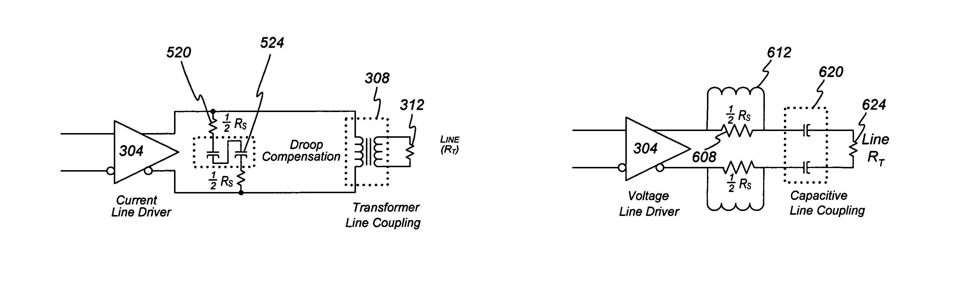
[0029]The common methods for reducing transmitter droop in applications that require high-voltage line isolation, discussed above as prior art, exhibit disadvantages that include bandwidth inefficiency, error multiplication, high manufacturing cost, poor high-frequency response, increased power consumption, and / or increased transmitter distortion. The present invention overcomes these disadvantages by frequency shaping of the input return loss response to improve the low-frequency signal coupling of a line interface circuit itself. Input return loss is determined by the ratio of the magnitude of a signal that enters a line isolation circuit to the magnitude of the signal that is reflected back from the line isolation circuit to the sou...


PUM


Abstract

As part of a transmitter and receiver system a droop compensator is provided between the channel isolation device and the driver system to compensate for reduced transition densities. The droop compensator is configured to improve power transfer to the channel in response to reductions in transition density without affecting power transfer during periods of high transition density. The droop compensator creates an impedance mismatch between the matching circuit and driver in relation to the line impedance. The droop compensator may comprise passive elements, such as capacitors, inductors, or resistor, or active elements including transistors or power control modules. The droop compensator may be configured to operate with transformer line couplers or capacitor line couplers, and either current drivers or voltage drivers.

Description

PRIORITY CLAIM[0001]This application claims the benefit of and priority to U.S. Provisional Patent Application No. 61 / 188,819 entitled Method and Apparatus for Reducing Transmitter AC-Coupling Droop filed on Aug. 12, 2008.FIELD OF THE INVENTION[0002]The invention relates to communication systems and in particular to a method and apparatus for transmitter droop compensation in communication systems that employ line / channel interfaces with AC-coupling.RELATED ART[0003]In wireline electronic communication applications, it is sometimes necessary to isolate sensitive, low-voltage circuitry from high-voltage disturbances that can arise directly from unintended coupling to power mains, due to physical shorts in a wire conduit, or indirectly from lightning surges. Industry standards governing telephony and computer networking (Ethernet) systems commonly refer to this as line isolation. Transformers with isolated primary and secondary windings, and high-voltage capacitors, are commonly used ...

Claims


Application Information

Patent Timeline
Patent Type & Authority Patents(United States)
IPC IPC(8): H03B1/00
CPCH04L25/0278H04L25/0284H04L25/0298
Inventor PAGNANELLI, CHRIS
Owner MARVELL ASIA PTE LTD
Why Eureka
Try Eureka