High sensitivity passive wireless strain sensor

a strain sensor, high sensitivity technology, applied in the field of strain sensors, can solve the problem that existing strain sensors do not have a passive wireless function, and achieve the effect of stable characteristic and simple manufactur

Active Publication Date: 2012-01-31
PUERTO RICO UNIV OF
View PDF14 Cites 44 Cited by
  • Summary
  • Abstract
  • Description
  • Claims
  • Application Information

AI Technical Summary

Benefits of technology

[0007]It is an objective of this invention to provide a low-cost, planar-structure strain sensor which is simple to manufacture, stable in character

Problems solved by technology

However, the existing strain sensors

Method used


Image

  • High sensitivity passive wireless strain sensor
  • High sensitivity passive wireless strain sensor
  • High sensitivity passive wireless strain sensor

Examples


Embodiment Construction

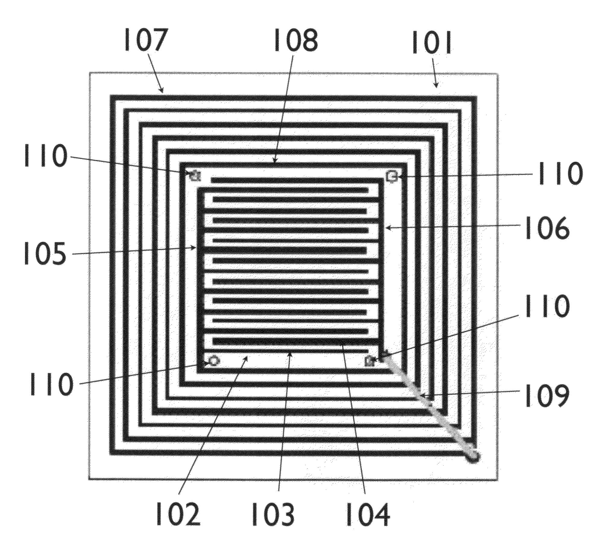
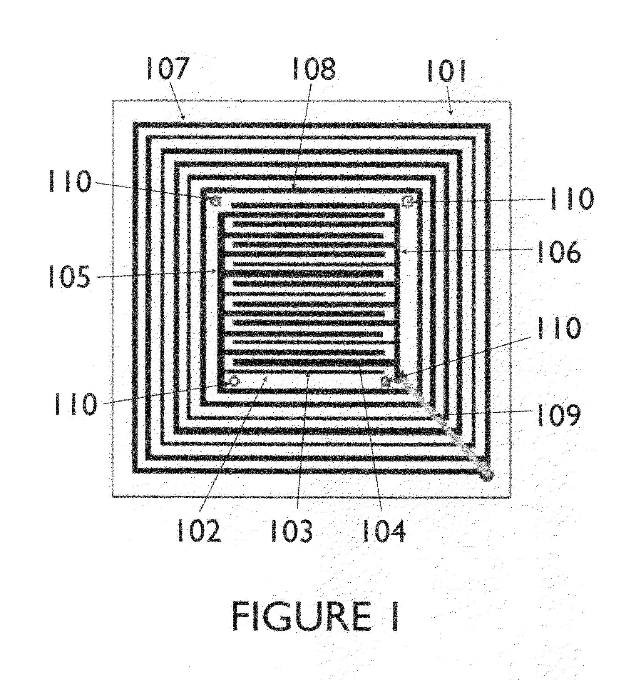
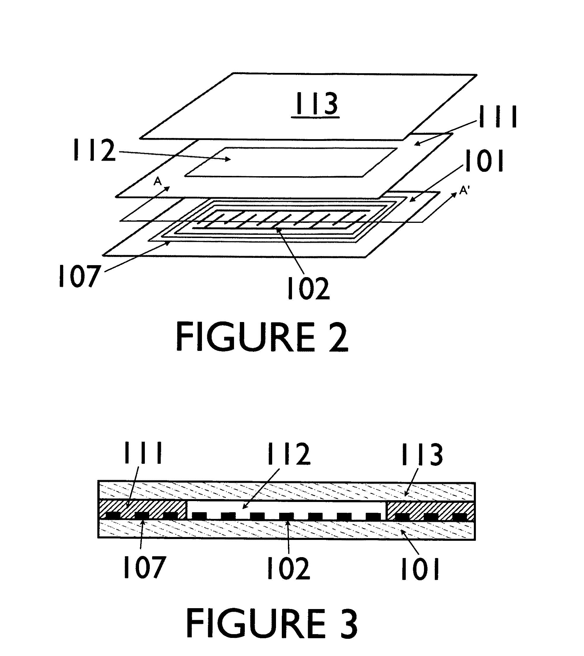
[0019]A capacitive strain sensor is formed using a three-layer structure. The first layer is relatively thin. As part of the first layer, an interdigitalized capacitor is formed on the top surface. In addition, an inductor is formed by a coiled conductor that surrounds the capacitor. In one preferred embodiment the capacitor has a square shape. The inductor is wound around the capacitor so that it also has a square shape. The capacitor and inductor are connected to form a simple, passive LC circuit with a resonant frequency. A second layer is positioned on top of the first layer. The second layer has a opening that approximately matches the shape of the capacitor. A third layer is positioned on top of the second layer. The opening in the second layer creates a cavity above the capacitor between the first and third layers.

[0020]When the top of the third layer is attached to a structure, deformations caused by strain will likewise deform the third layer of the structure. This changes ...


PUM


Abstract

A high sensitivity strain sensor that utilizes a micro-scale cavity built in a multi-layer structure, with a pair of interdigitalized capacitor incorporated on one of the layers, is described in this document. The device's capacitance changes produced by unattended deformations of the cavity can be used to measure the associated strain without using any movable electrodes. The sensor can be remotely energized from a radio frequency wave sent by a reader antenna to construct a battery-free wireless instrument. Changes on the sensor's resonant frequency are remotely detected so that a strain level is measured from fluctuations in the received signal. This detection method provides a simple, reliable and sensitive technique to measure small strain changes down to the pico-scale. Materials with a highly strain-dependant permittivity are integrated in the sensor to enhance its sensitivity. The proposed sensor consists of a simple planar structure. It can be used as the main component on low-cost, accurate and highly stable strain measuring instruments capable of monitoring very small strain levels. Furthermore, the sensor is passive, may be operated wirelessly, and can, thus, be used for remote long-term embedded strain detection.

Description

FIELD OF INVENTION[0001]The present invention relates to the general field of strain sensors. More particularly, the present invention relates to methods and devices to measure strain of engineering structures and mechanical components. Such techniques utilize thin diaphragms and Micro-Electro-Mechanical Systems (MEMS) structures and exhibit improved sensitivity and miniaturized dimensions.BACKGROUND OF THE INVENTION[0002]There are hundreds of types of capacitance sensors in use today. These sensors can be extremely sensitive and stable devices. Their operation is based on changes on the sensor's capacitance (c) according to formula 1, below:[0003]c=ɛ0⁢ɛr⁢Ad[1][0004]Such capacitance changes are induced by the quantity to be sensed. In our case, that is the applied strain. In the above expression, ∈0 is the free space permittivity (8.854×10⁻¹² C2 / Nm2), ∈r is the relative permittivity of the dielectric material between the electrodes, A is the surface area in m2 and d is the distance ...

Claims


Application Information

Patent Timeline
IPC IPC(8): G01B7/16
CPCG01B7/22G01L9/0072
Inventor JIA, YIJUST, FREDRICK A.TOLEDO-QUINONES, MANUELSERRANO, DAVIDSUN, KE
Owner PUERTO RICO UNIV OF
Why Eureka
Try Eureka