Method for joining at least a first member and a second member, lithographic apparatus and device manufacturing method, as well as a device manufactured thereby

a technology of lithographic apparatus and manufacturing method, which is applied in the direction of glass shaping apparatus, duplicating/marking methods, lamination, etc., can solve the problems of second member, fair failure chance, and unsatisfactory degradation of the bonding surface of the joined member

Active Publication Date: 2012-01-31
ASML NETHERLANDS BV
View PDF5 Cites 4 Cited by
  • Summary
  • Abstract
  • Description
  • Claims
  • Application Information

AI Technical Summary

Benefits of technology

[0010]It is an aspect of embodiments of the present invention to provide an alternative and / or improved method for joining at least a first and a second member, wherein particularly at least one of the members comprises ultra low expansion glass or ultra low expansion glass ceramics. It is also an aspect of embodiments of the invention to provide a method for joining at least a first and second member, in which the method is economical in terms of, for example, the amounts of materials, time, and / or money involved.
[0016]According to embodiments of the present invention, it is advantageous to combine direct-bonding with anodic bonding for joining at least a first and second member, wherein at least one the members comprises ultra low expansion glass or ultra low expansion glass ceramics. In direct-bonding, the first and second member are joined directly, contacting each other at respective bonding surfaces, without using any adhesive, glue or the like. Each of the members to be joined is solid during the direct-bonding process. The resulting, relatively weak, direct-bond is strong enough to hold the first and second member together. However, the direct-bond can be easily broken, without damaging the first and second member. It is generally believed that the direct-bond is achieved due to intermolecular van der Waals forces which come about between the first and second member when the first and second member are joined by their direct-bonding surfaces. As with anodic bonding, no adhesive is used in the direct-bonding process. Direct-bonding may be carried out, for example, at room temperature. Therefore, optical and material properties of the first and second member can be well-maintained during the direct-bonding process.
[0018]After the direct-bonding has been successful, the joined members are further bonded by anodic bonding, resulting in a stronger bond between the first and second member. For example, the anodic bonding may be used to strengthen the direct-bond which is already present.
[0021]Preferably, when one or more faults are found, the direct-bond is broken before the anodic bonding is carried out. The breaking of the direct-bond can be carried out relatively easily, since the strength of that bond is relatively low. Then, after the breaking of the direct-bond, the detected fault or faults may be removed, whereafter the first and second member are joined again by direct-bonding. Preferably, the resulting direct-bond is inspected yet again according to the afore described method, until a good direct-bond has been observed. The anodic bonding of the first and second member is preferably only carried out when no or substantially no faults are detected anymore. Therefore, the first and second member are only connected firmly to each other after they have been properly joined by direct-bonding. In this way, failure of the anodic bonding may be prevented, so that the first and second member can be joined economically. Such substantially fault free bonding of the first and second member may uphold or lead to certain desired properties of the first and second member, for example, certain materials properties, optical properties, properties relating to diffraction, reflection and / or transmission of one or more radiation beams, and the like.
[0027]Therefore, the lithographic apparatus part can be formed economically, using at least one bond which may be relatively strong, free from degassing adhesives, as well as substantially contamination free, wherein certain desired materials and / or optical properties of the members are obtained and / or maintained. The first and second member can be joined with high precision, for example, with a certain alignment, leading to an accurate manufacturing of the lithographic apparatus part. The resulting lithographic apparatus part may provide for a high precision manufacturing of devices, during use of the lithographic apparatus in a device manufacturing method.
[0036]Such device can be manufactured relatively economically, particularly inexpensively, and with high precision.

Problems solved by technology

Therefore, frit fusion and thermal fusion may lead to an undesired degradation of the bonding surfaces of the joined members, for example, from materials or optical point of view.
A disadvantage of the known method for joining at least a first member and a second member is that it has a fair chance of failure.
For example, it is relatively difficult to obtain a desired anodic bond between the first and second member having a substantially clean bonding surface.
The contamination may impair certain desired properties of the first and second member, for example, optical properties, properties relating to diffraction, reflection and / or transmission of a radiation beam, and the like.
The contamination may also impair material properties of the first and second member concerning, for example, a desired homogeneity, crystal structure, and the like.
The trapped contamination may lead to material defects, surface distortions, dislocations and / or cracks of the first and / or second member at the time of bonding or after they have been joined together using anodic bonding.
Such defects may occur after the anodic bonding, for example, during further treatment or processing of the joined members, such as during a subsequent removal of material from one or more of the joined members.
Moreover, the material defects may lead to a further degradation of desired optical properties of the first and / or second member.
One or more contaminating particles may damage the first an / or second member such that the anodically bonded members are unusable and have to be discarded, thereby leading to a waste of materials, time and money.
In case the members are found to be misaligned after the bonding process, the members may also have to be discarded, as a result of having become unusable.

Method used


Image

  • Method for joining at least a first member and a second member, lithographic apparatus and device manufacturing method, as well as a device manufactured thereby
  • Method for joining at least a first member and a second member, lithographic apparatus and device manufacturing method, as well as a device manufactured thereby
  • Method for joining at least a first member and a second member, lithographic apparatus and device manufacturing method, as well as a device manufactured thereby

Examples


first embodiment

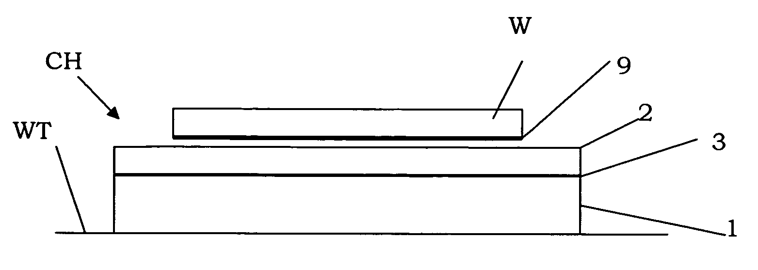
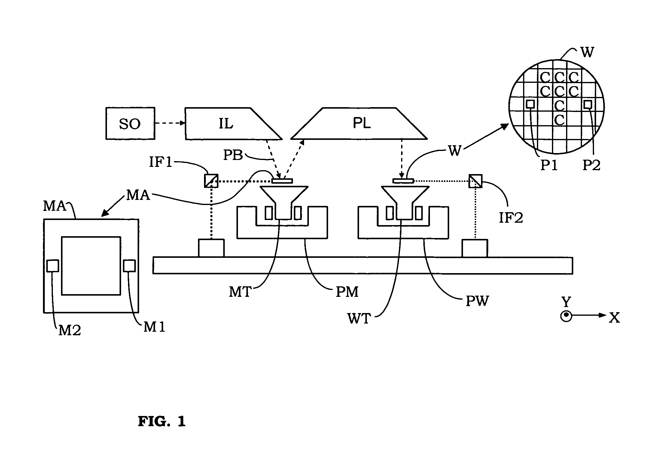
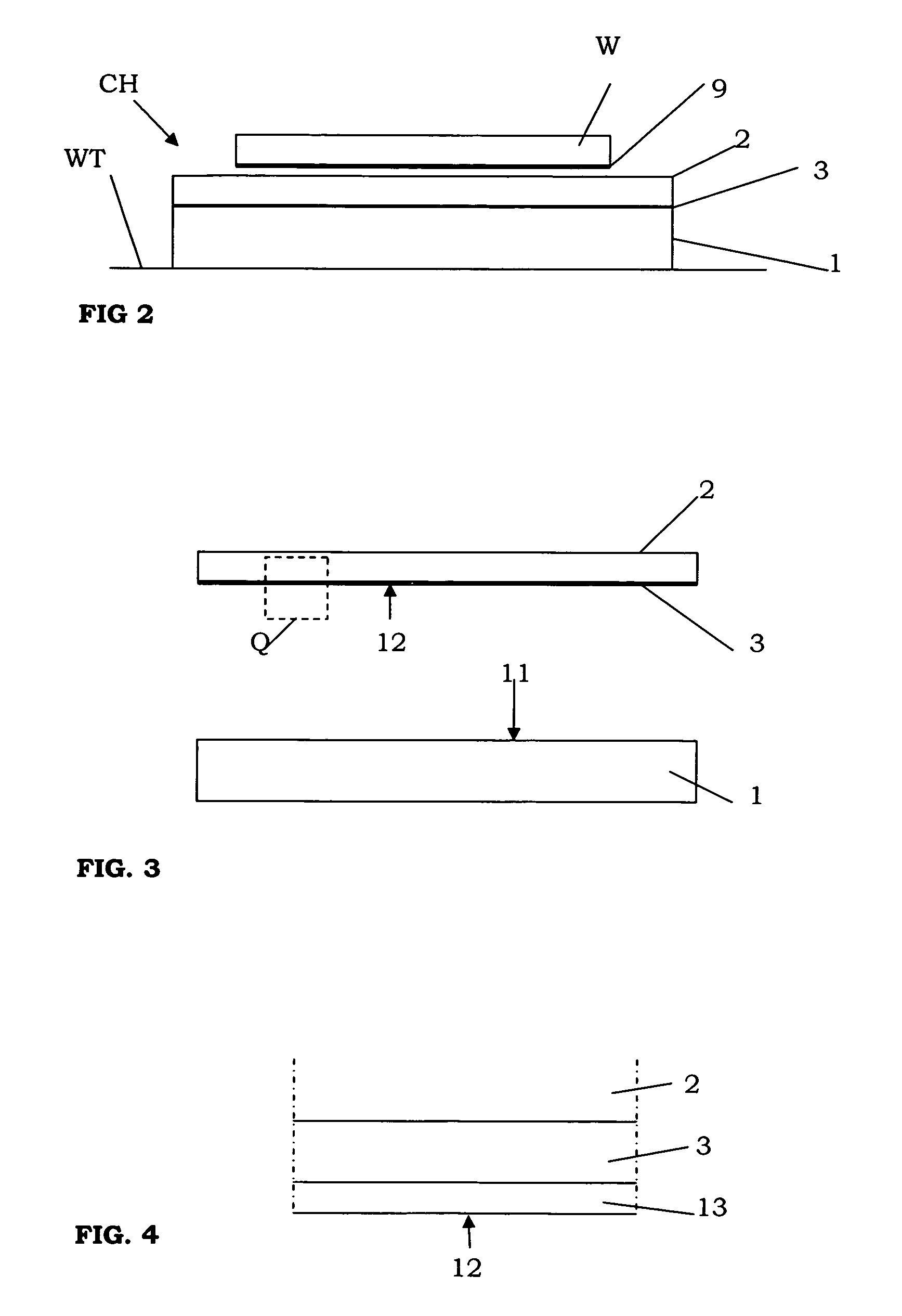
[0064]FIG. 2 shows the invention, comprising a chuck CH which may be used in the apparatus of FIG. 1. The chuck CH is not shown in FIG. 1. In the present embodiment, the chuck CH is used to hold substrates W onto the substrate table WT by electrostatic force. The chuck may also be used, for example, to hold the reticle onto the reticle table.

[0065]The chuck CH of the first embodiment comprises a first member 1 and a second member 2. A first electrode 3 extends between the first and second member 1, 2. The first electrode is an electrically conductive layer 3. The electrically conductive layer 3 preferably comprises one or more suitable conducting substances, for example, copper, aluminium, titanium, silver, gold, chrome, alloys thereof, other metals, and / or other alloys.

[0066]Each of the members 1, 2 comprises a material which is selected from the group consisting of: ultra low expansion glass, and ultra low expansion glass ceramics. In the present embodiment, the first member 1 com...

third embodiment

[0085]The first and second member 101, 102 of the third embodiment have been bonded directly onto each other, at opposite bonding surfaces 111, 112, using direct-bonding. The resulting bond has been improved using a further anodic bonding of the first and second member 101, 102. As has been shown, an outer surface of the first member 101 has been provided with electrodes 103. The bonding surface 112 of the second member 102 has also been provided with electrodes 104, which extend between the first and second member 101102 after the direct-bonding of the members 101, 102. The electrodes 103, 104 are used in the anodic bonding. The anodic bonding is achieved by applying a potential difference between the electrodes 103, 104 to drive an ion current therebetween for forming an anodic bond at the bonding surfaces 111, 112, similar to the embodiment shown in FIG. 6.

[0086]While specific embodiments of the invention have been described above, it will be appreciated that the invention may be...


PUM

PropertyMeasurementUnit
wavelengthaaaaaaaaaa

Abstract

A method for joining at least two members of a lithographic apparatus is disclosed. The method includes providing a first member, providing a second member, direct-bonding the first member and the second member to form a direct-bond, and anodically bonding the first member and the second member. At least one of the members includes ultra low expansion glass and / or ultra low expansion glass ceramics.

Description

BACKGROUND OF THE INVENTION[0001]1. Field of the Invention[0002]The present invention relates generally to a lithographic apparatus. More specifically, the present invention relates to a method for joining at least a first member and a second member of the lithographic apparatus.[0003]2. Description of Related Art[0004]A lithographic apparatus is a machine that applies a desired pattern onto a target portion of a substrate. Lithographic apparatus can be used, for example, in the manufacture of integrated circuits (ICs). In that circumstance, a patterning device or structure, such as a mask, may be used to generate a circuit pattern corresponding to an individual layer of the IC, and this pattern can be imaged onto a target portion (e.g. comprising part of, one or several dies) on a substrate (e.g. a silicon wafer) that has a layer of radiation-sensitive material (resist). In general, a single substrate will contain a network of adjacent target portions that are successively exposed....

Claims


Application Information

Patent Timeline
Patent Type & Authority Patents(United States)
IPC IPC(8): B29C65/00G03F7/20
CPCG03F7/707G03F7/70808G03F7/70825G03F7/7095
Inventor VAN ELP, JAN
Owner ASML NETHERLANDS BV
Why Eureka
Try Eureka