
Liquid to liquid biological particle concentrator

a concentrator and liquid technology, applied in the field of filtration systems, can solve the problems of inability to detect at all, and the failure of existing systems, etc., and achieve the effect of high efficiency and rapid cleaning

Active Publication Date: 2012-02-07
ALBURTYLAB
View PDF39 Cites 74 Cited by
  • Summary
  • Abstract
  • Description
  • Claims
  • Application Information

AI Technical Summary

Benefits of technology

"The present disclosure provides a highly efficient filtration system that can quickly clean and resuspend concentrated particles for analysis. The system uses a single or plural hollow fiber filters or other membranes in tangential flow devices. The filter is extracted using a small volume of foam, which is quickly returned to a liquid state when the foam collapses. The foam is made using a foam generator and can contain various additives. The system can be used with a variety of surfaces for capturing particles, such as membranes or immunomagnetic beads. The use of foam for extraction allows for efficient use of larger surface areas and reduces blinding of the membrane pore size. The system can also include concentration cells with membranes of different pore sizes for size fractionation."

Problems solved by technology

The difficulties of detecting and quantifying dilute materials in liquids are well known.
Existing systems all begin to fail as concentration falls away until, eventually with diminished concentrations of analyte, there is an inability to detect at all.
This poses a significant problem to national security where, for example, the postal anthrax attacks of 2001 and the subsequent war on terrorism have revealed shortcomings in the sampling and detection of biothreats.
Problems with the centrifugation technique limit its applicability.
The settling velocity of particles in the range of micron and smaller size particles is quite low and, consequently, centrifugal concentration of these particles takes several minutes to many hours.
It is also difficult to segregate the particles into size ranges.
One disadvantage of the physical barrier method of filtration is that the substance being filtered from the fluid will clog the channels through the filter over time.
Most such methods involve replacing the filter; however, if the filter is needed for a continuous process this need for replacement is highly problematic.
Scraping and in-situ cleaning mechanisms may be used, but these can be unnecessarily complex and expensive.
The biggest disadvantage of this method is the time requirement.
It is problematic that to date no automated methods have been developed that can rapidly concentrate a large volume of water into a very small sample volume and do this task efficiently.
In fact most of these methods fail in each of these areas, most notably efficiency of concentration, and ease of use.
Most of the methods described are not automated.
Generally these systems are capable of concentrating 10 to 100 L water into 100 to 500 mL of concentrated sample; however, it is further problematic that none of the demonstrated technologies provides concentration into volumes of less than 100 mL.
This means that a costly and time-consuming second manual concentration step is required to bring the final sample to the desired volume.
Advanced, rapid microbiological detectors used in these systems are only capable of analyzing volumes from around 40 μL to 200 μL of liquid at a time.
It is possible to measure foam in a metered volumetric quantity, but also it is difficult to do.
It can be difficult to push gas across a hollow fiber filter membrane, especially when liquid has reached that membrane.
Cleaning of these filters cannot be performed using ethyl acetate (typically used to dissolve polystyrene microspheres used for performance testing) or acetone, which dissolves PES.

Method used


Image

  • Liquid to liquid biological particle concentrator
  • Liquid to liquid biological particle concentrator
  • Liquid to liquid biological particle concentrator

Examples


working examples

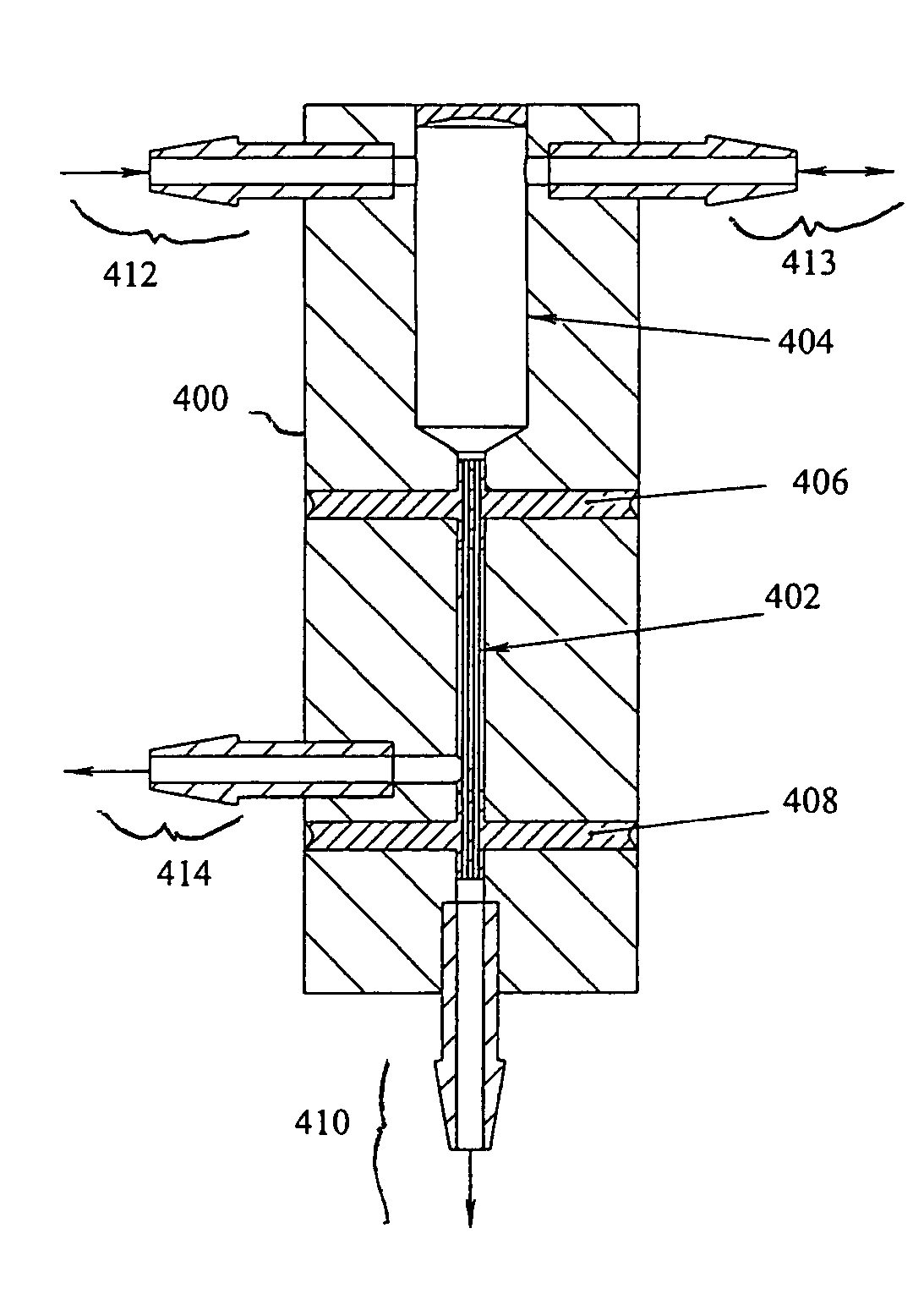
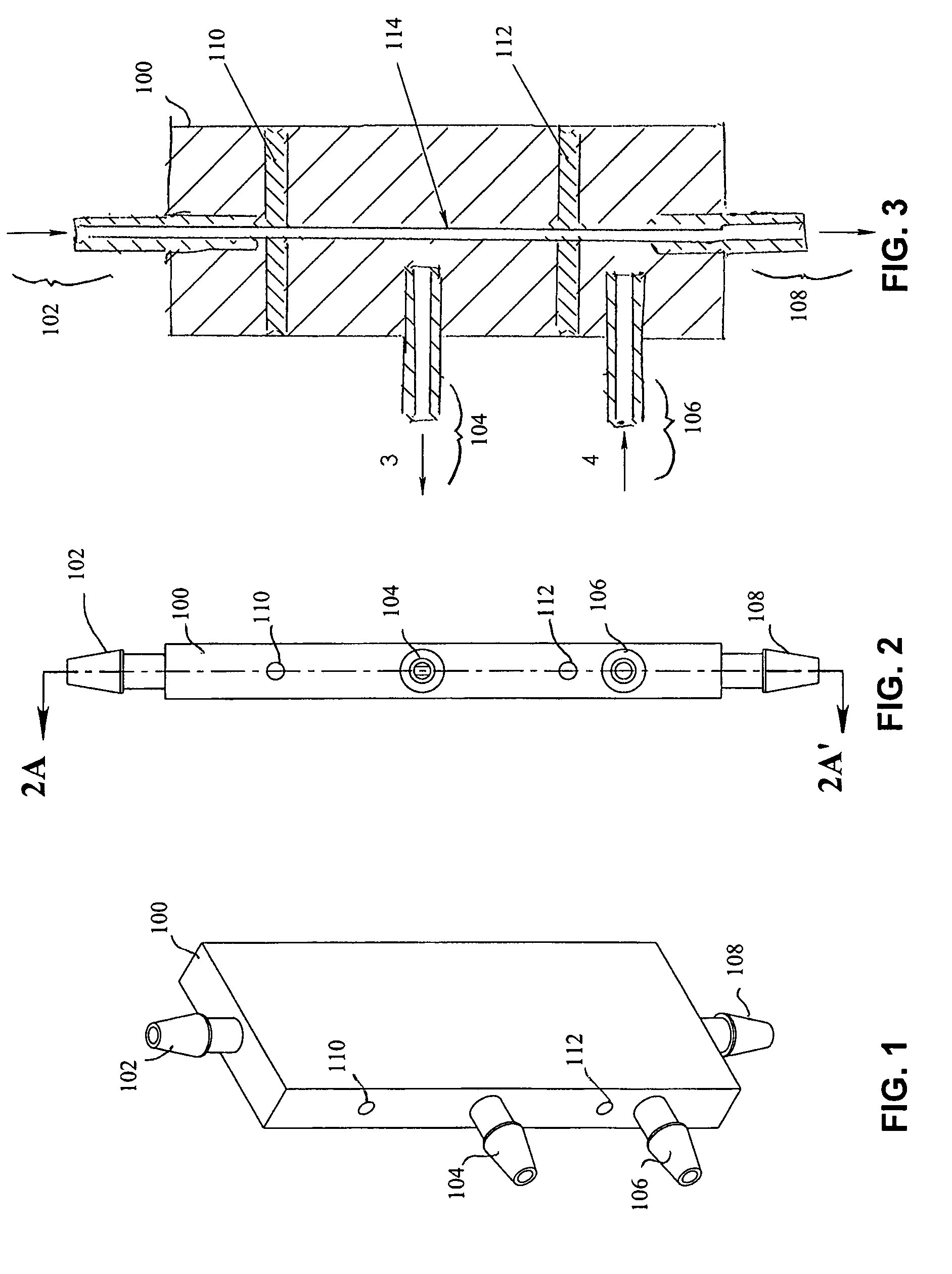
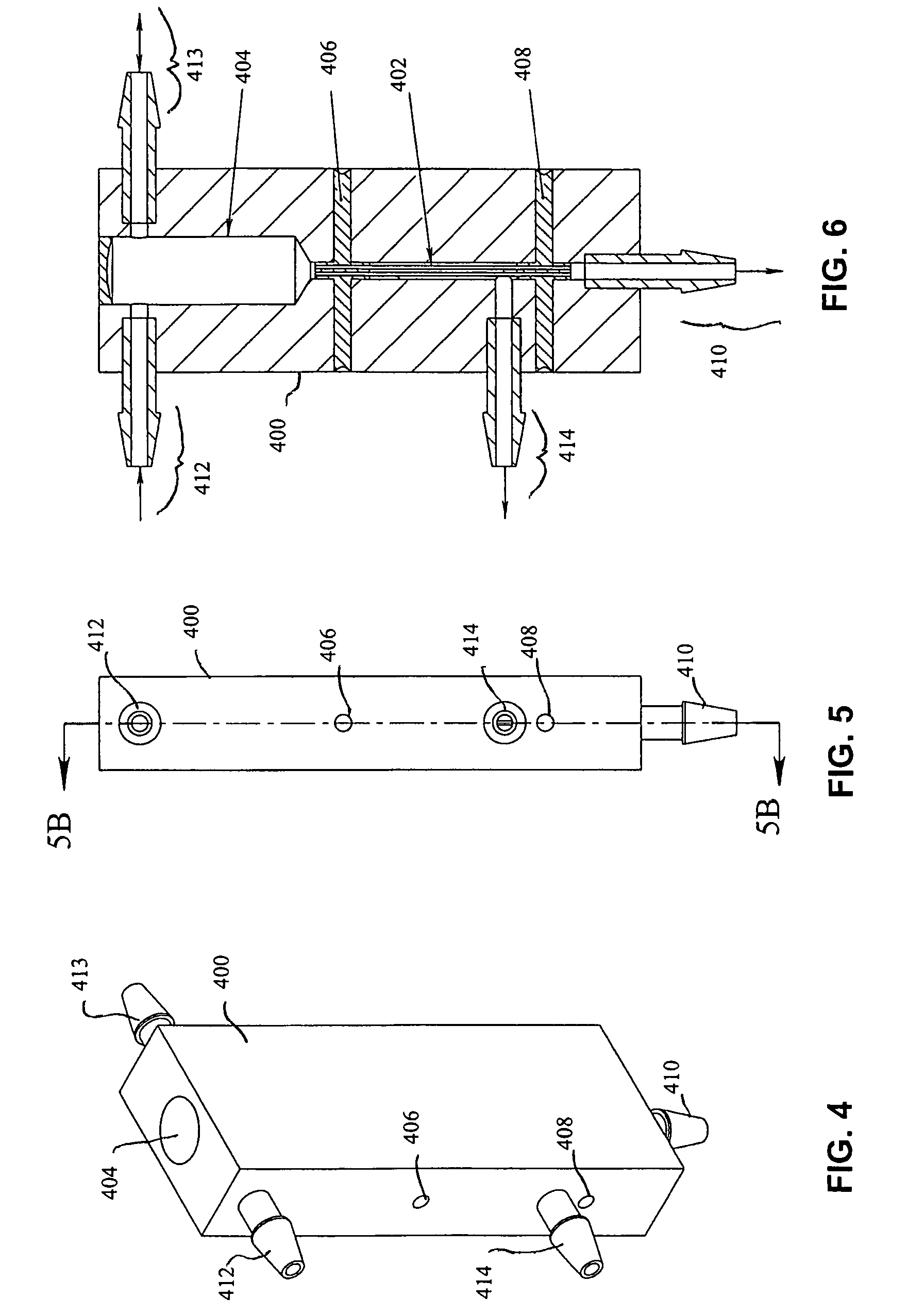
[0250]Performance testing of the device as shown in FIG. 1 above was conducted using carboxylate-coated yellow-green fluorescent polystyrene microspheres (Polysciences, Inc., Warrington, Pa.). Three sizes of microspheres were used; 1 micron, 3 micron, and 4.5 micron diameter. For each test run, 10 mL of a diluted microsphere suspension in water was used as feed. The results of nine 1-micron tests, eight 3-micron tests, and nine 4.5-micron tests were averaged, and the results are summarized graphically in FIG. 5. Note that these tests were performed without surfactant or shear added to the process, and the efficiency ranged from approximately 40% to 65%. Testing of the device was then performed with the addition of 0.01% Triton X-100 surfactant, improving the efficiency of the device to nearly 100%. Efficiency improvement data are shown in Table 1 below.

[0251]

TABLE 1Efficiency Improvement using SurfactantCondition number 16: 3 um carboxylate-coated YG microspheresCell efficiency impr...


PUM

PropertyMeasurementUnit
volumeaaaaaaaaaa
volumeaaaaaaaaaa
volumesaaaaaaaaaa

Abstract

A rapid one-pass liquid filtration system efficiently concentrates biological particles that are suspended in liquid from a dilute feed suspension. A sample concentrate or retentate suspension is retained while eliminating the separated fluid in a separate flow stream. Suspended biological particles include such materials as proteins / toxins, viruses, DNA, and / or bacteria in the size range of approximately 0.001 micron to 20 microns diameter. Concentration of these particles is advantageous for detection of target particles in a dilute suspension, because concentrating them into a small volume makes them easier to detect. Additional concentration stages may be added in “cascade” fashion, in order to concentrate particles below the size cut of each preceding stage remaining in the separated fluid in a concentrated sample suspension. This process can also be used to create a “band-pass” concentration for concentration of a particular target size particle within a narrow range.

Description

RELATED APPLICATIONS[0001]This application claims benefit of priority to U.S. Provisional Application Ser. Nos. 60 / 932,271 filed May 30, 2007 and 60 / 961,391 filed Jul. 20, 2007, both of which applications are hereby incorporated by reference to the same extent as though fully replicated herein.BACKGROUND[0002]1. Field of the Invention[0003]The invention relates generally to the field of filtration systems. More particularly, the filtration system is used to concentrate dilute materials, such as biological particles, as may be useful in the arts of bioterrorism security, medicine, and environmental science.[0004]2. Description of the Related Art[0005]The difficulties of detecting and quantifying dilute materials in liquids are well known. Existing systems all begin to fail as concentration falls away until, eventually with diminished concentrations of analyte, there is an inability to detect at all. This poses a significant problem to national security where, for example, the postal ...

Claims


Application Information

Patent Timeline
Patent Type & Authority Patents(United States)
IPC IPC(8): B01D61/00B01D63/00B01D65/02
CPCG01N1/4077G01N1/4005C12Q1/24C12Q1/04G01N2001/4088
Inventor ALBURTY, DAVID S.PAGE, ANDREW E.PACKINGHAM, ZACHARY A.MARSKE, DANIEL B.
Owner ALBURTYLAB
Learn More