Device and method for controlling the pressure in an inflatable cuff of a blood pressure manometer

a technology of inflatable cuffs and manometers, which is applied in the field of devices and methods for controlling the pressure in inflatable cuffs can solve the problems of reducing the control signal of the pid controller, affecting the accuracy of blood pressure manometers, and challenging automatic control engineering

Active Publication Date: 2012-02-14
CNSYST MEDIZINTECHN
View PDF10 Cites 9 Cited by
  • Summary
  • Abstract
  • Description
  • Claims
  • Application Information

AI Technical Summary

Problems solved by technology

Conversely, when the blood flow into the extremity decreases during diastole with the heart in its fill-up phase, which would lead to a rise in the PG signal, the control signal of the PID controller decreases and causes the pressure applied to the finger to drop.
The control system described by Penaz presents a challenge to automatic control engineering.
These fa...

Method used


Image

  • Device and method for controlling the pressure in an inflatable cuff of a blood pressure manometer
  • Device and method for controlling the pressure in an inflatable cuff of a blood pressure manometer
  • Device and method for controlling the pressure in an inflatable cuff of a blood pressure manometer

Examples


Embodiment Construction

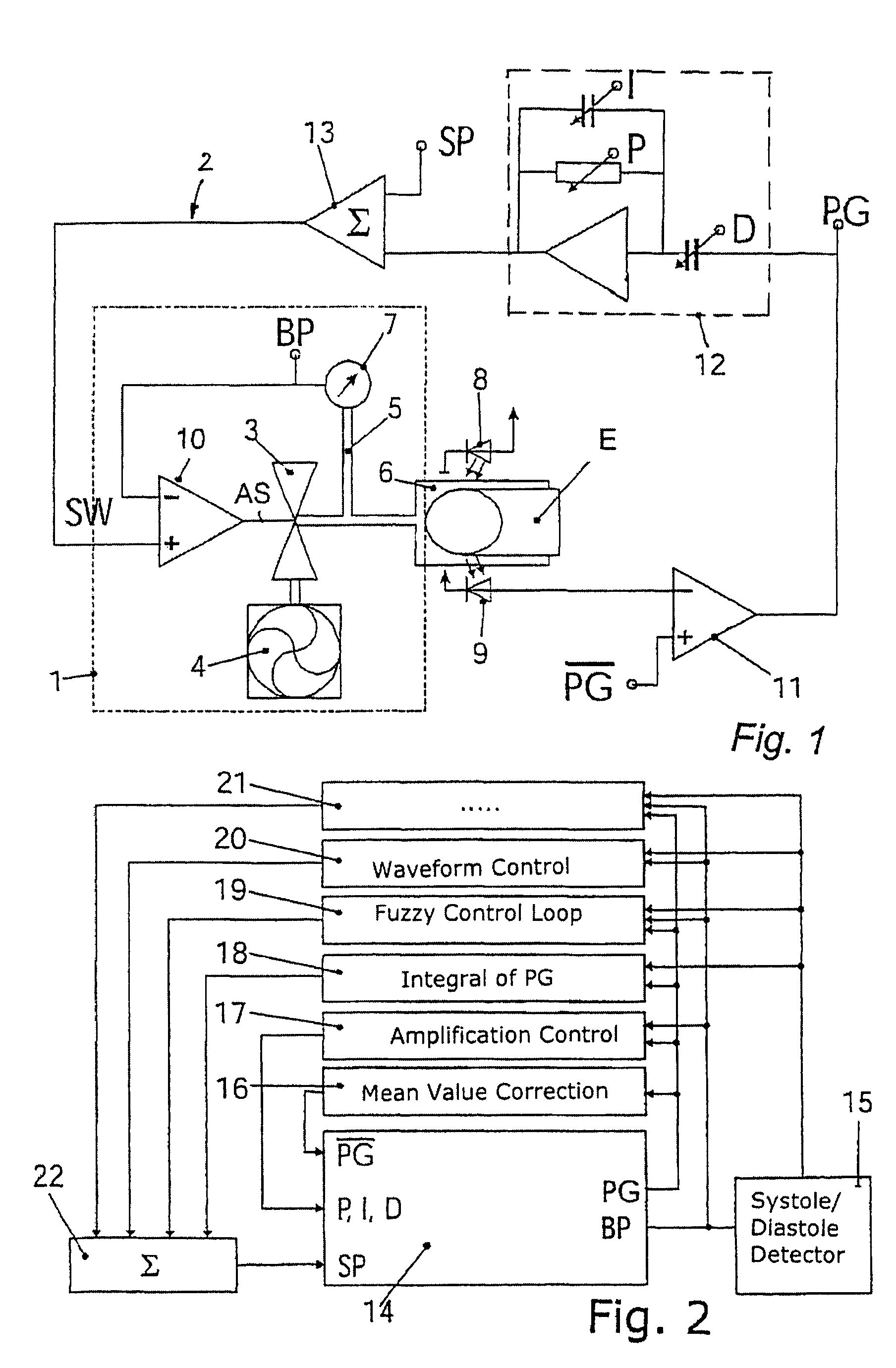
[0032]FIG. 1 shows a device for controlling pressure in an inflatable finger cuff 6 of a blood pressure measuring apparatus not further shown here. The control system consists of a first, inner control loop 1, which receives a target signal SW from a second, outer control loop 2. The inner control loop 1 comprises a difference amplifier 10 (preferably an operational amplifier), a proportional valve 3, which receives pressure from a pressure source, e.g. a pump 4, a pressure chamber 5 connected to the cuff 6, and a pressure sensor 7, which converts the pressure generated in the pressure chamber 5 or in the cuff 6 into an electrical signal BP, proportional to the cuff pressure. This electrical signal BP, which represents the intra-arterial pressure curve in the extremity E, is fed into the difference amplifier 10, whereby the first, inner control loop is closed. The difference amplifier 10 adjusts its output voltage AS in such a way that the voltage between its + input and its − input...


PUM


Abstract

The invention relates to a method and a device for regulating the pressure in at least one inflatable cuff, preferably a finger cuff (6), of a blood pressure manometer comprising a plethysmographic sensor device (8, 9) for detecting a plethysmographic signal PG and a pressure sensor (7) for detecting a cuff pressure signal BP. According to the invention, two control loops (1, 2) acting on a differential amplifier (10) are used to independently regulate different operating parameters, the first, inner control loop (1) using the cuff pressure signal BP as the first regulating variable, and the second, outer control loop (2) comprising a regulating device (12), preferably a PID regulator, which generates a nominal value SW as a second regulating variable from the plethysmographic signal PG. The differential amplifier (10) is connected, on the output side, to at least one valve connected to a pressure source (4), preferably a proportional valve (3; 25, 27), for regulating the pressure in the cuff (6). Additional outer control loops (16 to 21) can be used to respectively set a parameter of the device to a determined nominal value.

Description

BACKGROUND OF THE INVENTION[0001]1. Field of the Invention[0002]The invention relates to a device and a method for controlling the pressure in at least one inflatable cuff, preferably a finger cuff, of a blood pressure measuring apparatus provided with a plethysmographic sensoring device, where a plethysmographic signal PG and a cuff pressure signal BP are obtained.[0003]2. The Prior Art[0004]The continuous monitoring of blood pressure in an artery in a non-invasive way has for years been of interest to scientists and researchers. As early as in 1942 R. Wagner in Munich presented a mechanical system which was designed to measure arterial pressure of the arteria radialis by means of the so-called “vascular unloading technique”, which is also known as the principle of the relaxed arterial wall (Wagner R. “Methodik und Ergebnisse fortlaufender Blutdruckschreibung am Menschen”, Leipzig, Georg Thieme Verlag, 1942; Wagner R. et al. “Vereinfachtes Verfahren zur fortlaufenden Aufschrift des...

Claims


Application Information

Patent Timeline
IPC IPC(8): A61B5/02A61B5/0225
CPCA61B5/02255
Inventor FORTIN, JUERGENGRUELLENBERGER, RUPERTHACKER, ALEXANDERSKRABAL, FALKO
Owner CNSYST MEDIZINTECHN
Why Eureka
Try Eureka