Method for controlling the air system in an internal combustion engine

a technology of air system and internal combustion engine, which is applied in the direction of electrical control, process and machine control, instruments, etc., can solve the problems of different division of actuators, small controllery bandwidth, and impose marked restrictions, so as to improve the dynamic behaviour of closed loop combustion control, reduce noise, and optimise the effect of transient emissions

Active Publication Date: 2012-02-28
AVL LIST GMBH
View PDF4 Cites 3 Cited by
  • Summary
  • Abstract
  • Description
  • Claims
  • Application Information

AI Technical Summary

Benefits of technology

[0026]The method according to the invention allows the dynamic behaviour of the closed loop control of combustion to be improved and thus the complexity of the datafication with regard to the optimisation of transient emissions, noise, driving behaviour and driving comfort or torque behaviour to be significantly reduced.
[0027]With the aid of sensors for air mass, temp...

Problems solved by technology

A further drawback is that the given structures impose marked restrictions in the selection of the actuating element boundaries.
This gives rise to the problem that the controllery bandwidth is small and a different division of the actuators for other modes of operation is possible only to a limited extent.
Nevertheless, the filling of the cylinders...

Method used


Image

  • Method for controlling the air system in an internal combustion engine
  • Method for controlling the air system in an internal combustion engine

Examples


Embodiment Construction

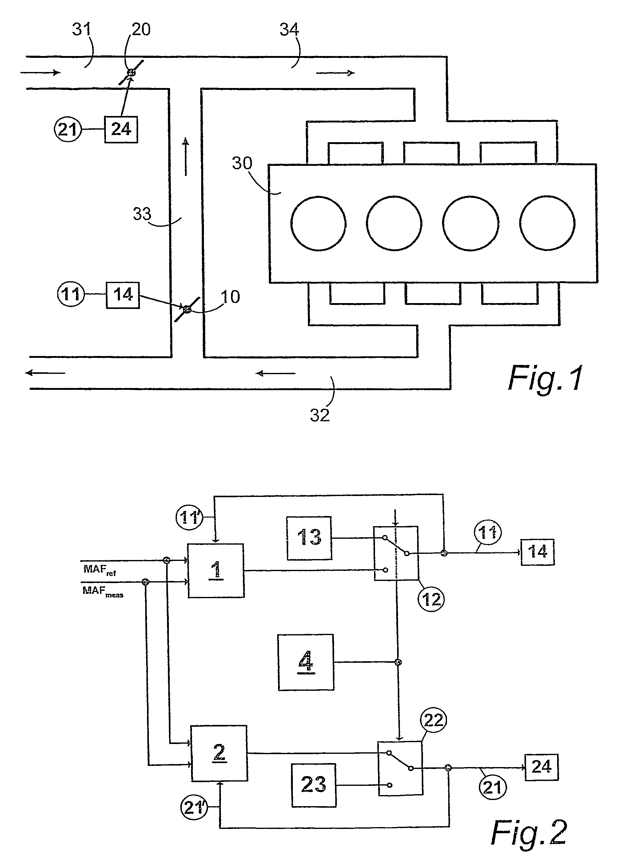
[0032]FIG. 1 is a schematic view of an internal combustion engine 30 with a fresh air tract 31, an inlet tract 34, outlet tract 32 and an exhaust gas recirculation tract 33, there being arranged in the exhaust gas recirculation tract 33 a first actuating element 14 actuating an exhaust gas recirculation valve 10 and in the fresh air tract 31 a second actuating element 24 actuating a throttle flap 20. Each actuating element 14, 24 has associated with it its own controller 1, 2. Also provided is a logic 4 which decides which of the two other controllers 1, 2 is activated or deactivated at each moment.

[0033]A target value for the mass air flow MAFref is determined. The target value for the mass air flow MAFref and the measured actual value of the air mass system MAFmeas are used as input variables for calculating the control deviation in the controller 1 for the exhaust gas recirculation valve 10 and the controller 2 for the throttle flap 20.

[0034]A strategic function implied by the lo...


PUM


Abstract

In a method for closed loop controlling the air system in an internal combustion engine, in particular a diesel internal combustion engine with a first actuating element for recirculated exhaust gas in the exhaust gas recirculation tract and a second actuating element for air in the inlet tract, the two actuating elements being adjusted as a function of each other. In order to increase the quality of closed loop control, provision is made for each actuating element to be controlled separately by its own respective controller, each controller being optimally configured for the respective controlled system, and a target value being provided for each controller.

Description

BACKGROUND OF THE INVENTION[0001]1. Field of the Invention[0002]The invention relates to a method for closed loop control of the air system in an internal combustion engine, in particular a diesel internal combustion engine, with a first actuating element for recirculated exhaust gas in the exhaust gas recirculation tract and a second actuating element for air in the inlet tract, the two actuating elements being adjusted as a function of each other, and also to a device for carrying out the method. Furthermore, the invention relates to a method for controlling the characteristic values of combustion in an internal combustion engine with at least one control path.[0003]2. The Prior Art[0004]U.S. Pat. No. 6,105,559 B discloses an inlet and exhaust gas recirculation system for an internal combustion engine, the actuators, the exhaust gas recirculation valve and throttle flap being actuated as a function of each other by a single actuating element (actuator). The two actuators are joine...

Claims


Application Information

Patent Timeline
IPC IPC(8): F02D9/00
CPCF02D9/02F02D35/023F02D41/0052F02D41/182F02D41/2432F02D41/2454F02D41/3064F02D2041/0017F02D2041/0022F02D2041/1418F02D2041/1426F02D2041/1427F02D2200/0402F02D2200/0408Y02T10/47Y02T10/40
Inventor RODUNER, CHRISTIANBACHINGER, MARKUSSTOLZ, MICHAELDANNINGER, ALOISNEUNTEUFL, KLEMENS
Owner AVL LIST GMBH
Why Eureka
Try Eureka