DC arc plasmatron and method of using the same

a plasmatron and arc technology, applied in plasma welding apparatus, gas-filled discharge tubes, manufacturing tools, etc., can solve the problems of limiting the wide use of plasmatrons for technologic purposes, high plasma contamination level with copper vapor and clusters, and the destruction of water-cooled anodes much more intensively, so as to improve the effect of process gas activation, increase the intensity and completeness of plasma-chemical reactions, and increase service tim

Inactive Publication Date: 2012-03-06
IND ACADEMIC COOPERATION FOUND JEJU NAT UNIVERSTIY
View PDF8 Cites 51 Cited by
  • Summary
  • Abstract
  • Description
  • Claims
  • Application Information

AI Technical Summary

Benefits of technology

[0010]It is an object of the invention to provide a plasmatron with improved effectiveness of process gas activation and increased intensity and completeness of plasma-chemical reactions therein. It is another object of the invention to provide a plasmatron with increased service time, high purity of generated plasma flow and possibility to operate it in vacuum with extended life time of the activated state for the technologic gas. and providing the clean technologic process.

Problems solved by technology

Water-cooled anodes are destroyed much more intensively.
In particular for copper that is often used to fabricate these parts, the erosion rate reaches 10−6 to 10−5 g / C which in turn limits service time of such plasmatrons to between 10° and 101 hours and results in a high level of plasma contamination with copper vapor and clusters.
These factors limit wide use of these plasmatrons for technologic purposes especially in the field of electronics.
This approach intended to lower the anode erosion rate but its effect turned out to be relatively small because this anode embodiment was also proved unable to change the destructive mechanism of the constricted anode arc spots.
This technology failed to provide high ability for the process gas activation because heating plasma forming gas in the anode area was non-uniform due to constricted nature of the anode spots.
As a result, the effectiveness of plasma-chemistry in the torch was not sufficient.
This method based on electrical breakdown of the inter-electrode space does not work in vacuum: according to the Paschen law in vacuum the discharge damages the parts like soldered seams, and collects cathode chucks, thin non-cooled elements, etc., that are never designed to be exposed to the action of arc spots.

Method used


Image

  • DC arc plasmatron and method of using the same
  • DC arc plasmatron and method of using the same
  • DC arc plasmatron and method of using the same

Examples


Embodiment Construction

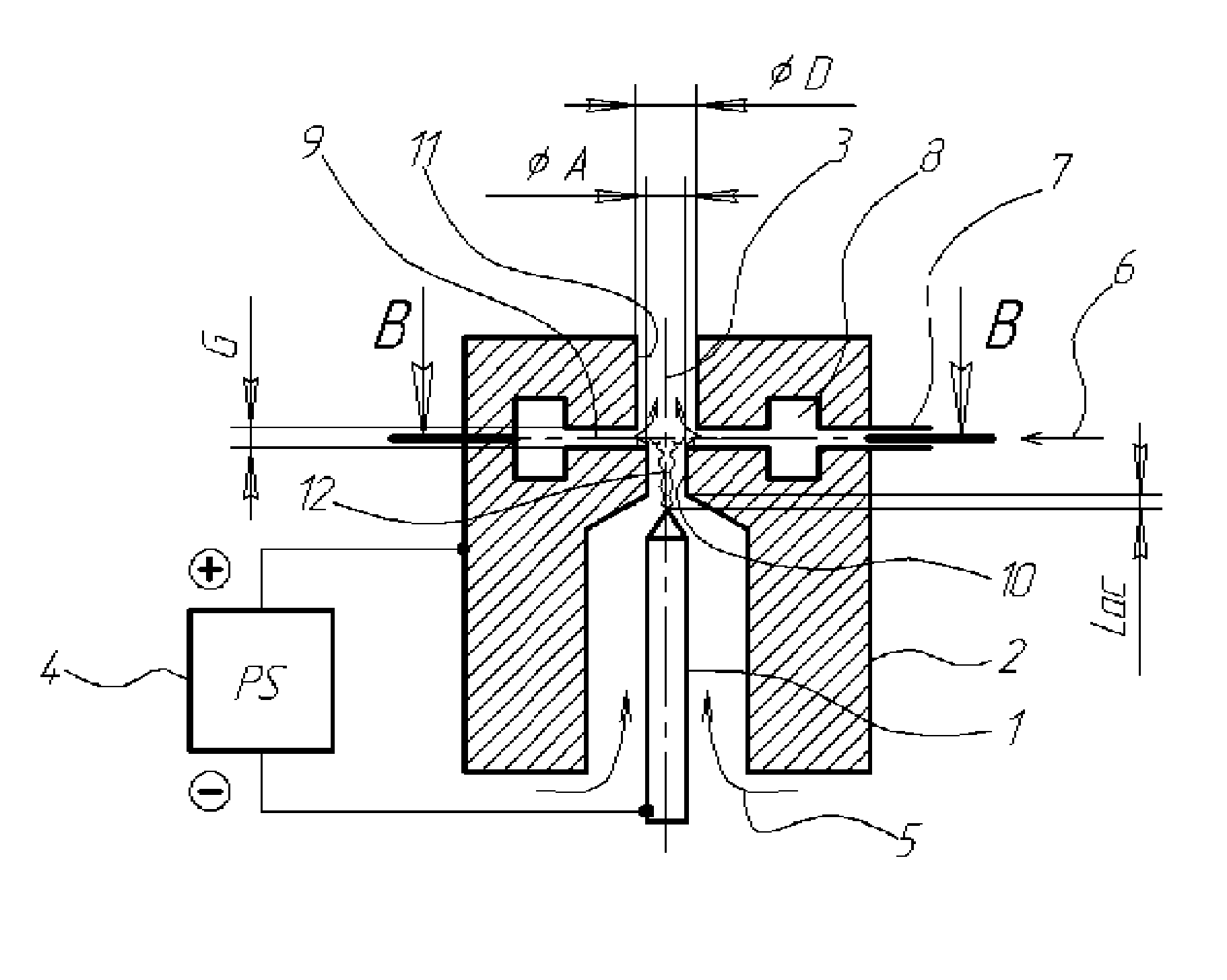
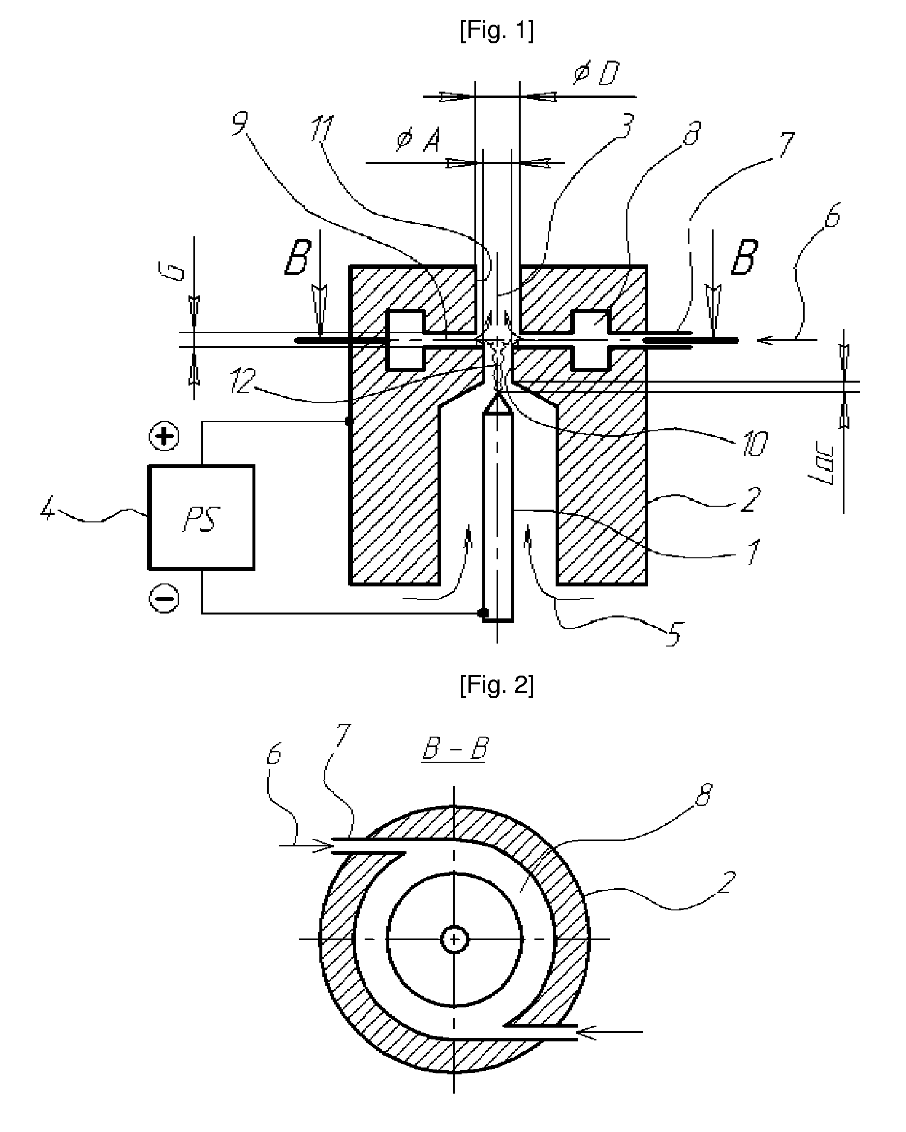
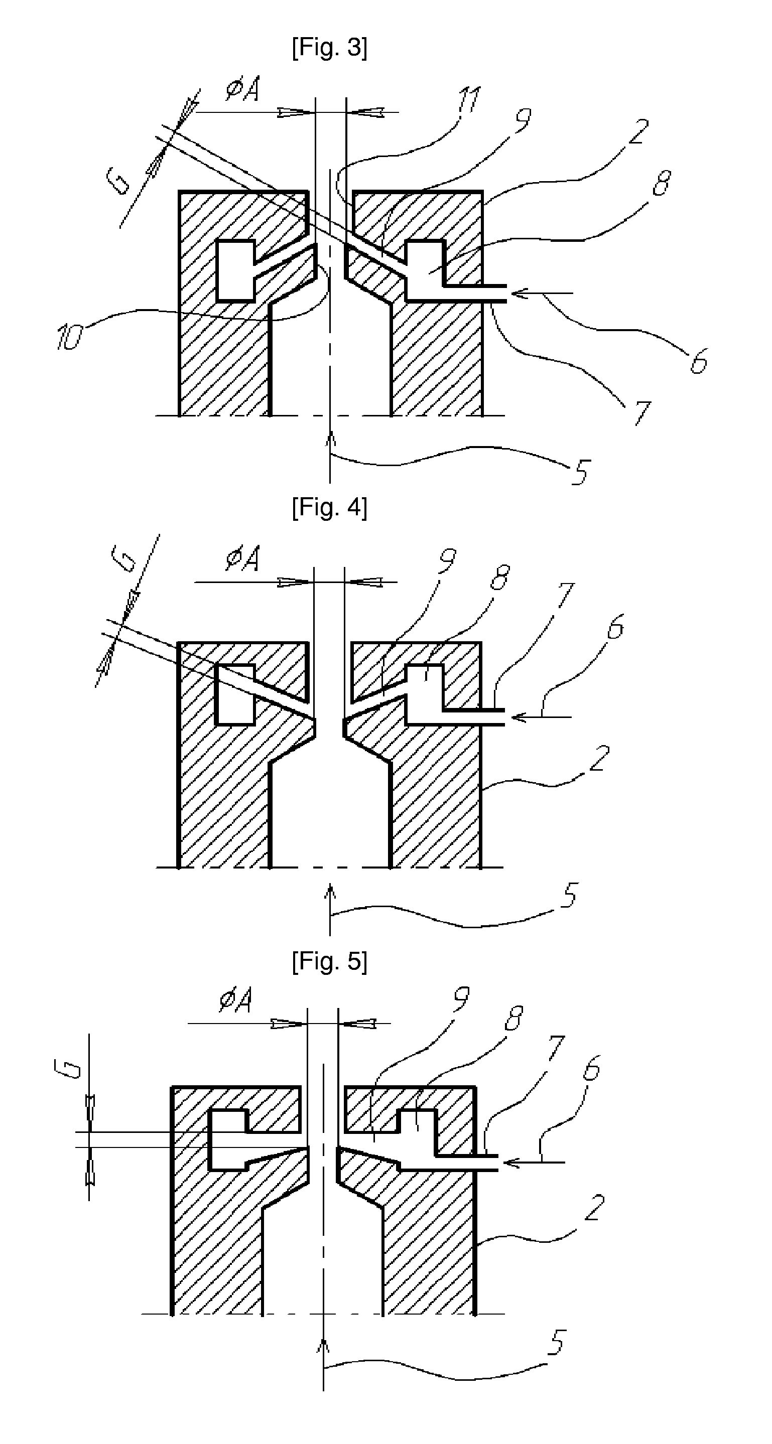
[0022]The proposed design of the anode body member 2 results in forming circular vortexes in the area where circular gap 9 communicates with the anode orifice 3. It is well known in the arc discharge physics (see for instance U.S. Pat. No. 6,114,649, 2000, by Delcea) that an anode spot is attracted with vortexes on the anode surface. Therefore the above mentioned intentionally generated vortex attracts arc anode spots to “smudge” or widen arc roots, distributing them over said circular surface which is much larger than the small surface where the conventional anode spots are concentrated. The concentrated anode spots cause the overheating of anode and quickly destroy bulk anode with an erosion rate of maximum 10−5 g / C.

[0023]The described distributed anode spot was not so far observed directly and reliably in an actual experiment. In accurate experimental studies, however, the inventive plasmatron showed that its anode erosion rate reached much lower level of about 10−10 g / C. The obt...


PUM

PropertyMeasurementUnit
temperatureaaaaaaaaaa
arc voltageaaaaaaaaaa
currentaaaaaaaaaa

Abstract

The present invention relates to a plasmatron structure for heating working gas in a DC arc discharge at the atmospheric or lowered pressures and can be used for different electronic, engineering, or vehicle-building industries and for medicine. An object of the invention is to provide improved effectiveness of process gas activation and increased completeness of plasma-chemical reactions. These objects are achieved in a DC arc plasmatron comprising a rod cathode, a nozzle anode having a body member and a through axial orifice, a power supply unit connected to both electrodes, and a gas system for feeding plasma-forming gas into inter-electrode space and supplying suitably selected technologic gas or gas mixture into the anode orifice through an internal opening communicating with said orifice and positioned between its inlet and outlet parts. In the plasmatron according to the invention, said opening is configured as a continuous circular axial gap between said parts of said anode orifice, while the size of said gap can be smaller or larger than the diameter of the inlet part of said anode orifice and the diameter of the outlet part of said anode orifice can also be smaller or larger than the inlet part of said anode orifice. In addition the inventive plasmatron can be successfully applied in vacuum conditions to extend lifetime of the activated process gas and to provide the clean treatment procedure.

Description

RELATED APPLICATIONS[0001]The present application is based on International Application Number PCT / KR2006 / 005693 filed Dec. 26, 2006, and claims priority from Korean Application Number 10-2006-0030688 filed Apr. 4, 2006, the disclosures of which are hereby incorporated by reference herein in their entirety.TECHNICAL FIELD[0002]The present invention relates to a DC arc plasmatron and a method of using the plasmatron in vacuum for startup with an HV / HF oscillator.[0003]More particularly, the invention relates to a plasmatron structure for heating working gas in a DC arc discharge at the atmospheric or vacuum pressures that can be used in electronic, engineering, or vehicle-building industries for plasma or plasma-chemical treatment of surfaces (cleaning, etching, deposition), cleaning vehicle / industrial exhausts, and in medicine for disinfection, sterilization of tools or biological objects, or applying hardening or protective coatings to increase wear resistance of tools or use organ...

Claims


Application Information

Patent Timeline
Patent Type & Authority Patents(United States)
IPC IPC(8): B23K10/00
CPCH05H1/24H05H1/48H05H1/3468A47G1/06A01K63/003A01G9/024B44C5/043B44C5/06A47G1/16H01J37/32055
Inventor LEE, HEON-JUMOK, YONG-SONRIABY, VALENTIN ANATOLIEVICHPLAKSIN, VALDIM YU
Owner IND ACADEMIC COOPERATION FOUND JEJU NAT UNIVERSTIY
Why Eureka
Try Eureka