Telescope with a wide field of view internal optical scanner

a scanner and telescope technology, applied in the field of telescopes with wide field of view internal optical scanners, can solve the problems of the inability to effectively use the prime power of the instrument, and the inability to achieve the capability through a simple scaling of the laser fire rate or power from spacecraft, etc., to achieve the effect of reducing the area of impa

Active Publication Date: 2012-03-27
INTERGRAPH
View PDF9 Cites 11 Cited by
  • Summary
  • Abstract
  • Description
  • Claims
  • Application Information

AI Technical Summary

Benefits of technology

[0016]One embodiment of the current invention relates to a scanning instrument including a fixed telescope and incorporating an optical dual wedge scanner comprising a first optical wedge, a second optical wedge, and a controller arranged to control a synchronous rotation of the first and second optical wedges. The wedges are constructed and arranged to scan laser light redirected by topological surfaces and / or volumetric scatterers, which redirect the light to a first converging optical element that receives the redirected light and transmits the redirected light to the scanner, and a second converging optical element within the light path between the first optical element and the scanner arranged to reduce an area of impact on the scanner of the beam collected by the first optical element.
[0017]One embodiment of the current invention relates to a scanning instrument including a fixed telescope and incorporating an optical dual wedge scanner comprising a first optical wedge, a second optical wedge, and a controller arranged to control a synchronous rotation of the first and second optical wedges. The wedges are constructed and arranged to scan the transmitted laser light across topological surfaces and / or volumetric scatterers, which redirect the light to a first converging optical element that receives the redirected light and transmits the redirected light to the scanner, and a second converging optical element within the light path between the first optical element and the scanner arranged to reduce an area of impact on the scanner of the beam collected by the first optical element.
[0019]Another embodiment of the current invention relates to a scanning instrument including a fixed telescope and incorporating an optical wedge scanner comprising a single optical wedge, and a controller arranged to control a rotation of the optical wedge. The wedge is constructed and arranged to scan laser light redirected by topological surfaces and / or volumetric scatterers, which redirect the light to a first converging optical element that receives the redirected light and transmits the redirected light to the scanner, and a second converging optical element within the light path between the first optical element and the scanner arranged to reduce an area of impact on the scanner of the beam collected by the first optical element.
[0020]Another embodiment of the current invention relates to a scanning instrument including a fixed telescope and incorporating an optical wedge scanner comprising a single optical wedge, and a controller arranged to control a rotation of the optical wedge. The wedge is constructed and arranged to scan the transmitted laser light across topological surfaces and / or volumetric scatterers, which redirect the light to a first converging optical element that receives the redirected light and transmits the redirected light to the scanner, and a second converging optical element within the light path between the first optical element and the scanner arranged to reduce an area of impact on the scanner of the beam collected by the first optical element.
[0021]Another embodiment of the invention relates to a 3D imaging system which incorporates a light source that can emit a beam of light, a telescope with internal scanner that includes an optical wedge scanner comprising a single optical wedge and a controller arranged to control a rotation of the optical wedge. The wedge is constructed and arranged to scan light redirected by topological surfaces and / or volumetric scatterers, a first converging optical element that receives the redirected light and transmits the redirected light to the scanner, and a second converging optical element within the light path between the first optical element and the scanner arranged to reduce an area of impact on the scanner of the beam transmitted by the first optical element. A detector module can be arranged to detect light collected by the telescope and generate signals responsive to the detected light, and a processor may be used to process signals generated by the detector.

Problems solved by technology

As a result of this conventional design philosophy, spacecraft prime power and weight constraints typically restrict operations to modest repetition rates on the order of a few tens of Hz which, for a typical earth orbit ground velocity of seven kilometers per second, limits along-track spatial sampling to one sample every few hundred meters.
There is a recognized need to obtain higher along-track resolution and / or better cross-track coverage, but achieving this capability through a simple scaling of the laser fire rate or power is not practical from spacecraft.
This is especially true of altimeters for use in orbit about other planets where instrument mass, volume, and prime power usage is severely restricted.
Furthermore, the conventional high signal-to-noise ratio approach to laser altimetry does not make efficient use of the available laser photons.
First generation altimetric approaches are not well suited to generating the few meter level horizontal resolution and decimeter precision vertical (range) resolution on the global scale desired by many in the Earth and planetary science communities.
On Earth, the presence of manmade buildings and volumetric scatterers (such as tree canopies or other vegetation) generally makes waveform interpretation even more complex and difficult.
One challenge to the conventional approach is the sheer number of measurements required over a nominal mission lifetime of two to three years.
If one were to simply scale conventional approaches, one would clearly face severe prime power, weight, and instrument longevity issues.
A second technical challenge is the high ground speed of the spacecraft (about 3 km / sec for a nominal 300 km altitude Mars orbit) coupled with the need to incorporate a scanner to cover the large area between adjacent ground tracks, especially near the equator.
While alternative non-mechanical scanners, such as electrooptic or acousto-optic devices, are capable of very high scanning speeds and have no moving parts, they typically fall far short of the angular range requirements, are highly limited in their useful aperture, and / or require fast high voltage or high RF power drivers.
An additional technical challenge stems from the high laser fire rate and the long pulse time of flight (TOF).
While such a navigation accuracy might be easy to achieve in Earth orbit using either Global Positioning System (GPS) receivers or Satellite Laser Ranging (SLR) to passive reflectors on the spacecraft, it would likely be a much more difficult challenge in orbits about extraterrestrial bodies.
An additional technical problem associated with the longer pulse TOF from orbit is related to “transmitter point-ahead”, i.e. the offset between the center of the laser beam at the surface and where the receiver is looking one 2 msec round trip transit time later.

Method used


Image

  • Telescope with a wide field of view internal optical scanner
  • Telescope with a wide field of view internal optical scanner
  • Telescope with a wide field of view internal optical scanner

Examples


Embodiment Construction

[0032]While the invention has been shown and described with reference to a particular embodiment thereof, it will be understood to those skilled in the art, that various changes in form and details may be made therein without departing from the spirit and scope of the invention.

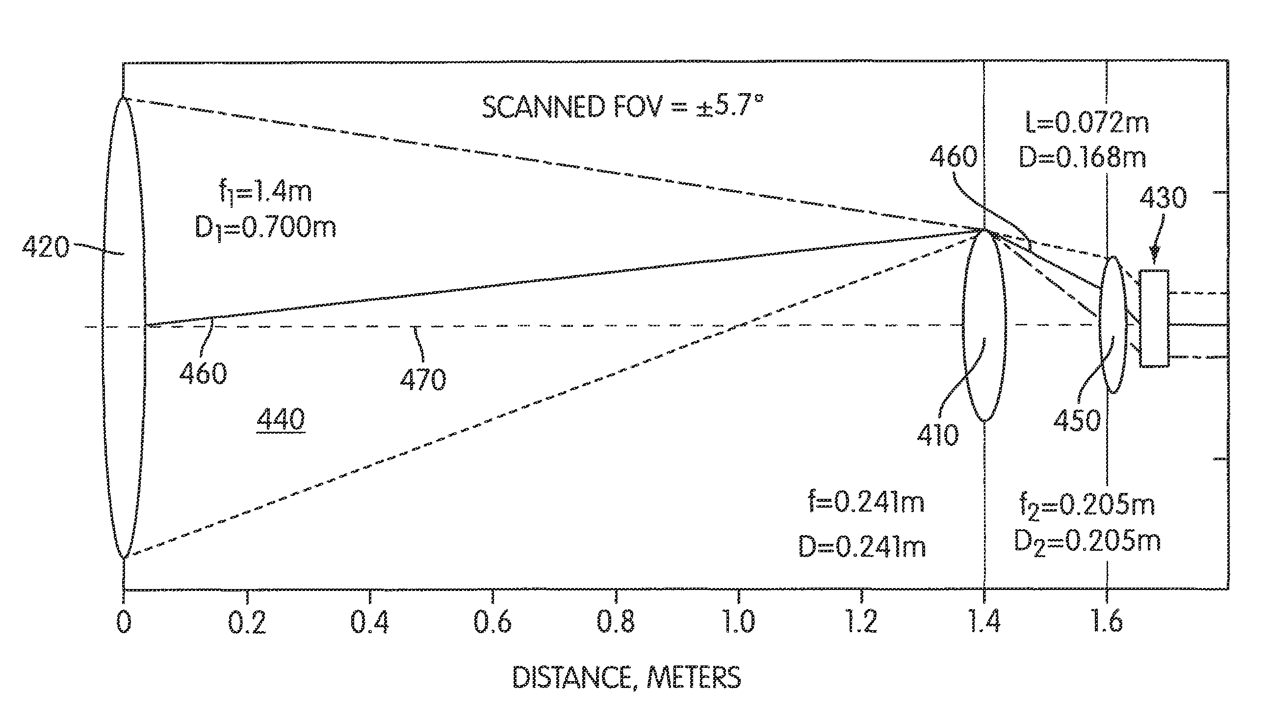
[0033]As indicated above, one practical way to generate a continuous topographic map of topographic surfaces from an airborne or spaceborne platform is to use an array of laser beamlets scanned at high speed over the topographic surface and to collect the laser light redirected by the surface into a telescope with internal scanner arranged to feed a photon-counting, focal plane, detector array matched to the array of laser beamlets. In scanner embodiments for spaceborne applications, scanners incorporating uniformly rotating optical elements may be desirable at least because of their inherent simplicity in design, operation and control, reliability, and low power consumption. In the case of embodiments using ...


PUM


Abstract

A telescope with internal scanner utilizing either a single optical wedge scanner or a dual optical wedge scanner and a controller arranged to control a synchronous rotation of the first and / or second optical wedges, the wedges constructed and arranged to scan light redirected by topological surfaces and / or volumetric scatterers. The telescope with internal scanner further incorporates a first converging optical element that receives the redirected light and transmits the redirected light to the scanner, and a second converging optical element within the light path between the first optical element and the scanner arranged to reduce an area of impact on the scanner of the beam collected by the first optical element.

Description

STATEMENT REGARDING FEDERALLY SPONSORED RESEARCH AND DEVELOPMENT[0001]This invention was conceived using US Government funding under NASA Contract No. NHH05CC68C entitled “A Scanning Active Laser Altimeter / Polarimeter and Passive Hyperspectral Imager for Globally Contiguous, High Resolution Mapping of the Jovian Moons”. The US government has certain rights in this invention.BACKGROUND OF THE INVENTION[0002]The invention relates generally to the integration of scanning optical sensors with telescopes. In particular, the invention relates to telescopes with wide field of view internal optical scanners. In particular embodiments, the telescope with internal scanner may be part of an active imaging LIDAR system or passive optical sensor for use onboard an aircraft or spacecraft.[0003]In one embodiment, a telescope with an internal optical scanner permits high speed scanning over a wide angular field of view (several degrees) while simultaneously providing a narrow instantaneous field of...

Claims


Application Information

Patent Timeline
Patent Type & Authority Patents(United States)
IPC IPC(8): G01C3/08H01J3/14G02B26/08
CPCG01C3/04G01J3/02G01J3/0208G01J3/0224G01J3/36G02B23/06G02B26/108H01L27/14601H01L27/14625G02B23/14
Inventor DEGNAN, III, JOHN JAMESZHENG, YUNHUI
Owner INTERGRAPH
Why Eureka
Try Eureka