

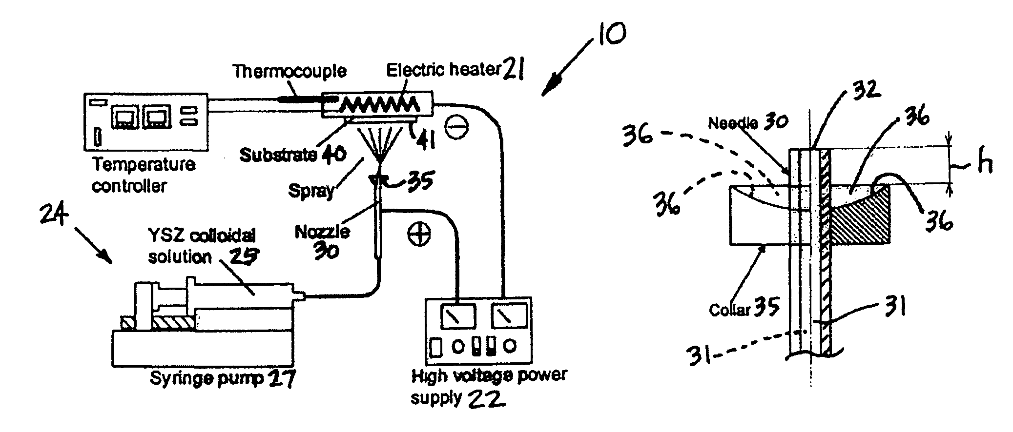
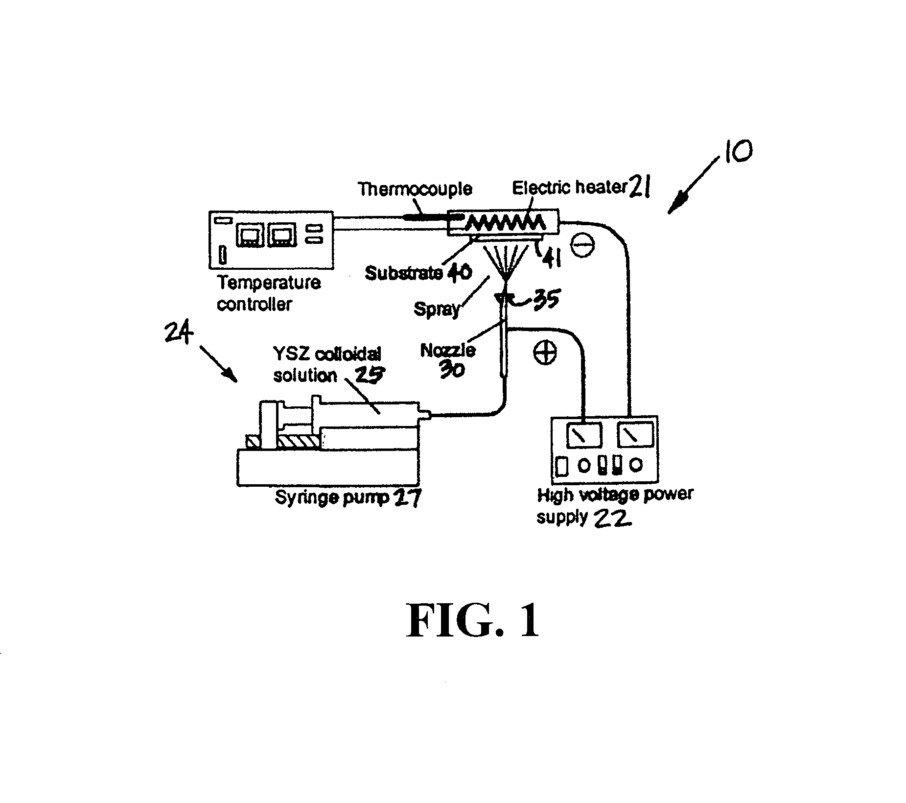
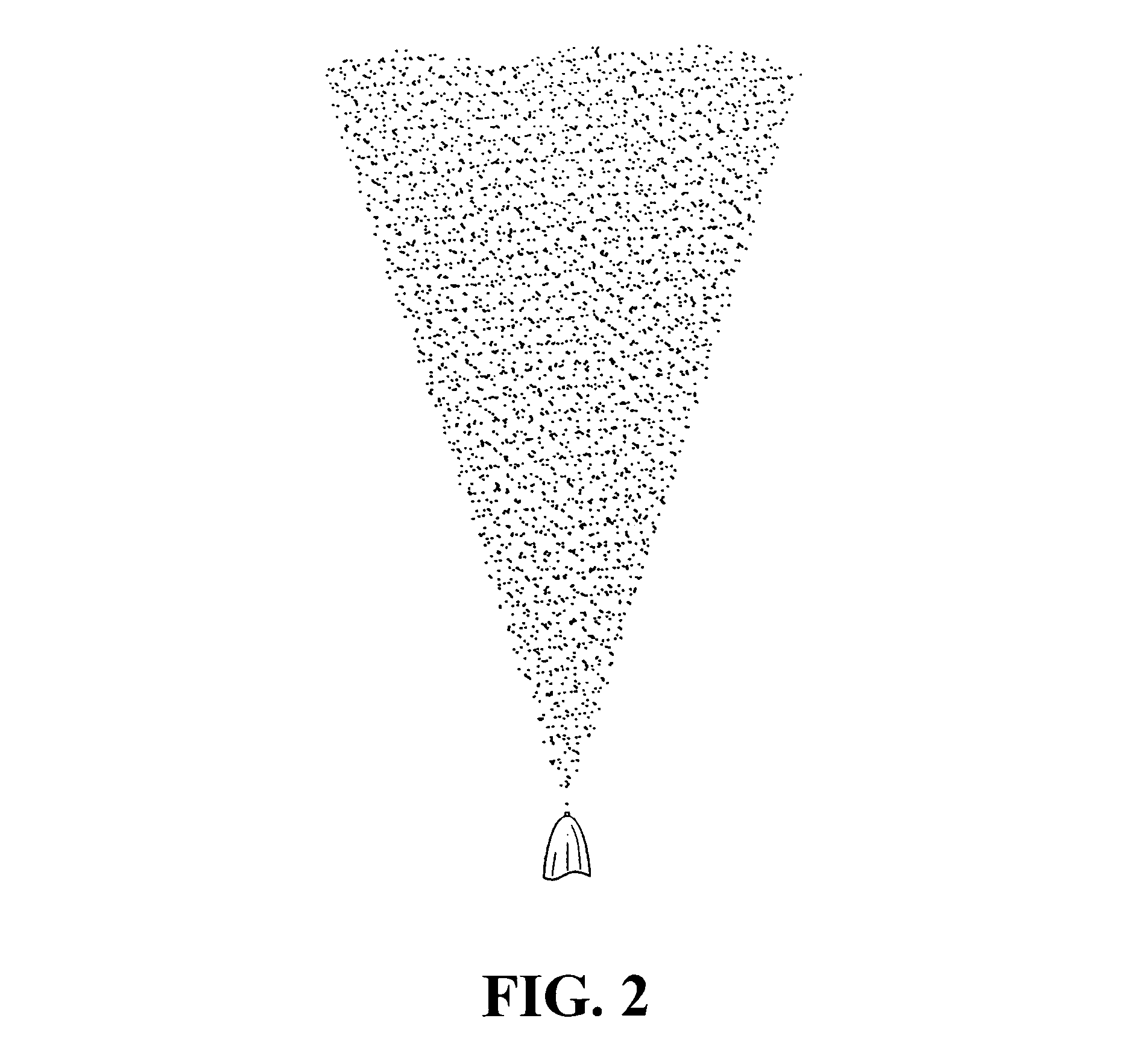
Method and apparatus for electrostatic spray deposition for a solid oxide fuel cell
a fuel cell and electrostatic spray technology, applied in the direction of cell components, final product manufacturing, sustainable manufacturing/processing, etc., can solve the problems of not being 100% or completely dense, requiring post-process annealing, and the category 1 process lacks the required quality associated with deposit microstructure, etc., to achieve good control of the morphology of the deposited layer, simple set-up, and large film growth ra
- Summary
- Abstract
- Description
- Claims
- Application Information
AI Technical Summary
Benefits of technology
Problems solved by technology
Method used
Image

Examples
Embodiment Construction
[0041]YSZ deposition can be conducted using suspensions of YSZ powder in organic fluids. ESD is a versatile technique that can be adapted to both solutions and suspensions or emulsions, and to various organic and mixed aqueous / organic solvents or electrolyte solutions. For YSZ depositions, there are two main possibilities. One possibility is to use spray deposition from a solution of a precursor. Another possibility is to use colloidal or near-colloidal suspensions of YSZ or of yttria and zirconia separately. Each approach has its own merits.
[0042]In one embodiment of this invention, a colloidal suspension of YSZ is used. Advantages of ESD using a colloidal solution include: (1) that no chemical reaction occurs during the dispersion and deposition process, and thus optimization of operating conditions is simpler and the chemical composition of the deposit is a priori uniform; (2) that low-temperature operation is adequate because breakdown or reaction of precursors, requiring high g...
PUM
| Property | Measurement | Unit |
|---|---|---|
| thickness | aaaaa | aaaaa |
| temperature | aaaaa | aaaaa |
| specific ionic conductivity | aaaaa | aaaaa |
Abstract
Description
Claims
Application Information