Marine energy hybrid

a hybrid energy and marine technology, applied in the direction of wind motors with solar radiation, electric generator control, machines/engines, etc., can solve the problems of eliciting considerable social resistance, presenting a particularly acute challenge, and limited land area for land-based wind farms

Inactive Publication Date: 2012-05-08
ROE JUSTIN C +1
View PDF8 Cites 25 Cited by
  • Summary
  • Abstract
  • Description
  • Claims
  • Application Information

AI Technical Summary

Benefits of technology

[0016]It is an object of the present invention to provide a marine energy hybrid more powerful per unit of area than any individual marine-based technology.
[0018]Another object of the present invention is to provide a marine energy hybrid with a radically extended lifespan than that of existing technologies by distributing load forces over a larger area, reducing wear, and eliminating failure-prone components such as generator gearboxes.
[0019]Yet another object of the present invention is to provide lower capital, installation, and maintenance costs compared with those of wind, wave, and marine current systems individually by leveraging the use of a common platform.
[0020]Still another object of the present invention is to provide a marine energy hybrid with lower environmental, navigational, and visual impact than that of competing technologies individually.
[0021]It is the aim of the present invention to synergistically combine a diversity of marine energy producing elements in such a fashion that the resulting hybrid outperforms any of said elements individually. Accordingly, the desired outcome is to increase power output from the same surface area, more reliably, at lower cost, and with reduced environmental impact.

Problems solved by technology

In the harsh marine environment, each of these factors presents a particularly acute challenge.
Second, land-based wind farms are limited by available land area, and elicit considerable social resistance due to perceived “visual blighting” of the landscape.
Unfortunately, these offshore wind installations have encountered substantial obstacles.
There are physical issues, as well.
Due to the economically-driven trend towards extremely large blade rotor diameters, and the resultant concentrated stresses at the blade roots, hub and gear mechanisms, component failures requiring expensive overhaul are common.
This high rate of wear also directly affects turbine lifespan which is currently projected to be approximately 20 years.
A further consequence of these stress loads is that conventional wind turbines are approaching the upper limits of unit size, which increases the footprint area of the wind farm for any given output.
First, the horizontal spokes serve no constructive aerodynamic purpose; in fact, they contribute only parasitic drag, which limits turbine efficiency.
Additionally, as the diameter of the turbine increases, the mass of said horizontal spokes increases in a non-linear fashion, further limiting turbine efficiency, and ultimately structurally limiting the overall diameter and output of the turbine.
Second, supporting the turbine assembly on a central hub concentrates load forces over a small bearing surface, which causes significant wear, and consequently reduces system lifespan.
Consequently, the theoretical scale of the hubless VAWT is virtually unlimited.
It should be noted, however, that in practical terms the cost of an offshore floating hubless VAWT may be prohibitively great.
Another unavoidable aspect of offshore wind farms common to all marine-based systems is the necessity for power transmission back to land.
High voltage submarine electricity cables or Hydrogen gas pipelines represent a significant capital cost which directly affects profitability.
Because the output of an individual conventional wind turbine is relatively small, the energy transmission network linking multiple units is complex and extensive, resulting in substantial costs and environmental impact.
A controversial, but nonetheless valid environmental concern is that of bird kill.
At issue is the fact that although they are rotating at only 13.4 rpm, and although the blade roots are clearly visible, the slender blade tips of a 100 m diameter HAWT rotor travel at 252 Km / h, inhibiting blade visibility at the outer region of the swept area, and increasing the likelihood of collision.
The major drawback to wind farms is their unpredictable intermittency.
Despite a multitude of proposed designs over the past 200 years, practical development has been stymied by the emergence and exploitation of cheap, relatively convenient fossil fuels.
Despite the promise of wave energy converters, the vast majority of existing designs share a common set of drawbacks that negatively affect capital and operational costs.
First, almost without exception, WECs are very material intensive.
Another disadvantage of present designs is they tend to consist of fields of multiple units, similar to wind farms.
Consequently, large areas are occupied, mooring and power transmission networks are extensive, shipping navigation is impeded, and maintenance of individual units at sea involves high risk and expense.
Another tendency of WEC designs is that towards complexity of mechanical-to-electrical conversion.
Ocean current converters share some of the limitations common to wind and wave devices.
These include a reliance on large areas of deployment necessitating extensive mooring and transmission networks, and high risk, expensive maintenance of individual units.
In addition, ocean current poses some unique design challenges.
Among these is the biofouling of slender hydrofoils which reduces efficiency and increases maintenance costs.

Method used


Image

  • Marine energy hybrid
  • Marine energy hybrid
  • Marine energy hybrid

Examples


Embodiment Construction

[0044]The presently preferred embodiment of the invention will be best understood by reference to the drawings, wherein like parts are designated with like numerals throughout.

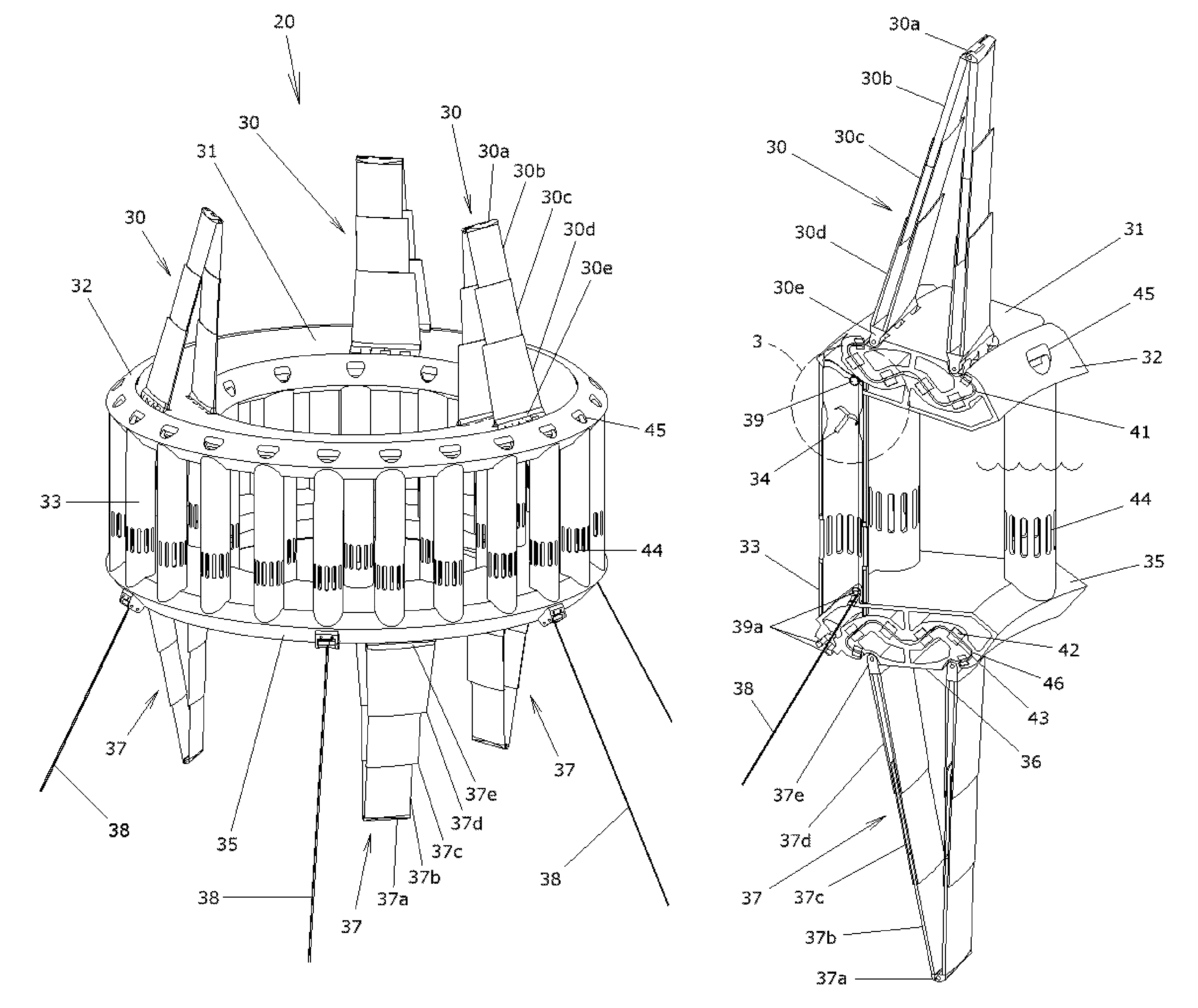
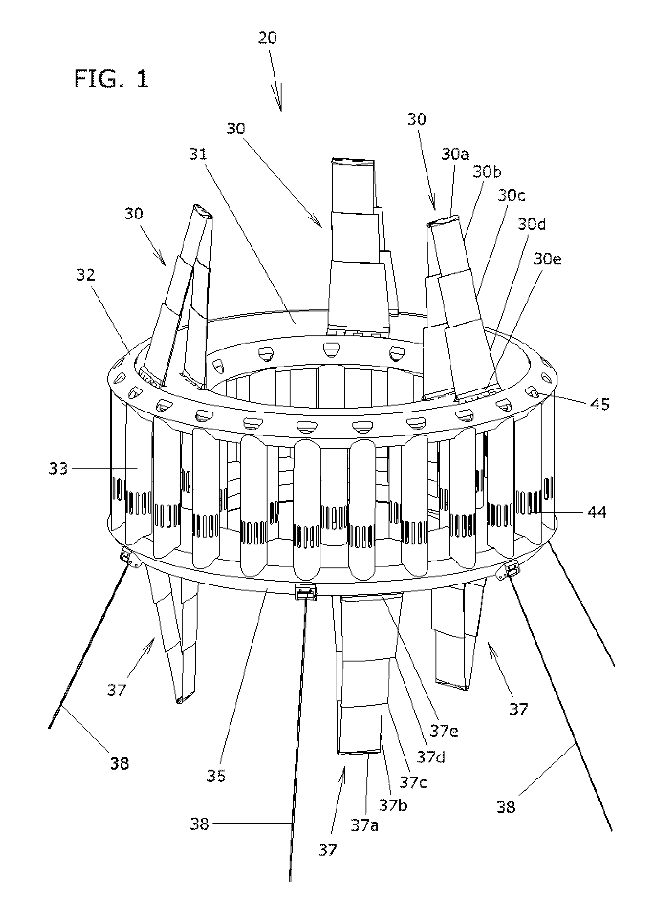
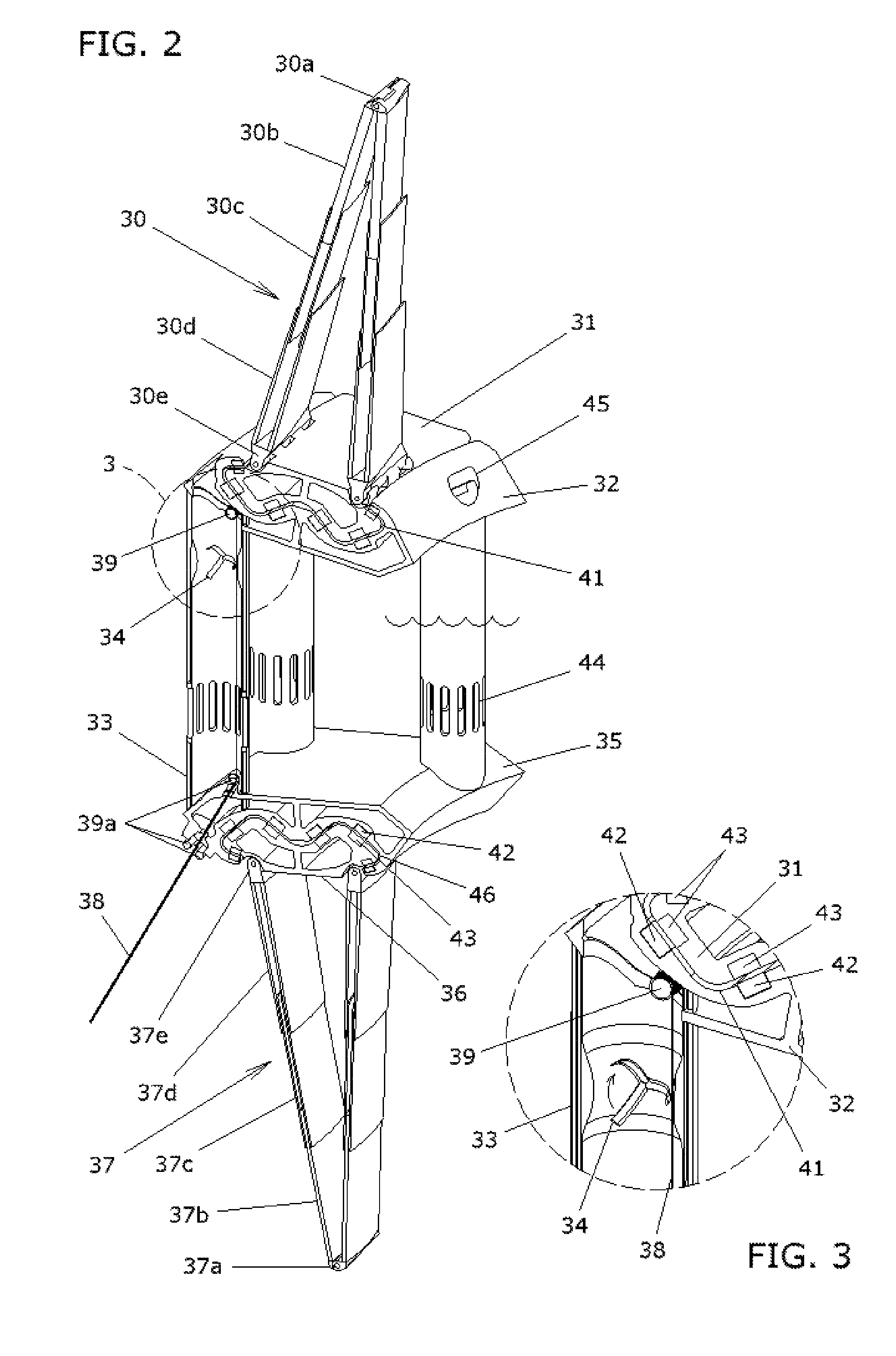
[0045]With reference to FIGS. 1, 2 and 3, a marine energy hybrid device or system 20 of the present invention is illustrated. Marine energy hybrid device 20 includes a central, non-rotatable or fixed member or ring 32 with an upper rotatable carriage element 31 rotatably mounted at an upper track assembly 41 of fixed member 32 and a lower rotatable carriage element 36 rotatably mounted at a lower track assembly 46 of a lower fixed member or ring 35. At least one vane assembly 30 is mounted to and extends upwardly from upper carriage element 31 for rotating upper carriage element 31 relative to fixed member 32 in response to the wind stream, while at least one vane assembly 37 is mounted to and extends downwardly from the lower carriage element 36 for rotating lower carriage element 36 relative to fixed member ...


PUM


Abstract

A marine energy hybrid includes a support structure locatable at or near the surface of a body of water and at least two of (a) a hubless upper carriage movable along an upper track of the support structure with at least one wind vane mounted at the upper carriage to induce motion of the upper carriage relative to the support structure by reaction with the wind stream, (b) a hubless lower carriage movable along a lower track of the support structure with at least one water vane mounted at the lower carriage to induce motion of the lower carriage relative to the support structure by reaction with the water current, and (c) at least one wave energy conversion device integral with the support structure and operable to generate electrical or mechanical power in response to wave motion of the body of water.

Description

CROSS-REFERENCE TO RELATED APPLICATIONS[0001]This application claims the benefit of U.S. provisional patent applications Ser. No. 60 / 806,836 filed Jul. 10, 2006, and Ser. No. 60 / 828,957 filed Oct. 10, 2006, which are hereby incorporated herein by reference in their entireties.BACKGROUND OF INVENTIONField of Invention[0002]The present invention relates to wind, wave and ocean current energy systems and in particular to synergistic hybrids thereof.BACKGROUND OF THE INVENTIONComponent Technologies[0003]As the quest for clean, abundant and secure energy supply intensifies, attention is being increasingly directed to marine sources such as wind, waves and ocean currents. Each of these resources is a concentrated kinetic form of solar energy capable of providing a significant share of global human demand. A multitude of technologies has emerged to harness and convert these powerful forces. Every technical proposal is subject to the same realities, namely that to be economically viable, it...

Claims


Application Information

Patent Timeline
Patent Type & Authority Patents(United States)
IPC IPC(8): F03D5/04
CPCF03B13/16F03B13/264F03B17/066F03D5/04F03D9/008F05B2240/93Y02E10/28Y02E10/38Y02E10/70Y02E10/72F03D9/007F03D13/25F03D80/70Y02E10/30Y02E10/727Y02E10/20
Inventor ROE, JUSTIN C.YOUNT, MICHAEL H.
Owner ROE JUSTIN C
Why Eureka
Try Eureka