Method and system for compensation of a carrier frequency offset in an OFDM receiver

a carrier frequency offset and receiver technology, applied in the field of processing orthogonal frequency division multiplexed (ofdm) signals, can solve the problems of carrier frequency determination and correction, inter-carrier interference (ici), and severe increase in the bit error rate (ber) of recovered data at the receiver, so as to facilitate the constructive averaging of pilot phase information and clean frequency offset estimation

Active Publication Date: 2012-05-22
INTERDIGITAL MADISON PATENT HLDG
View PDF29 Cites 96 Cited by
  • Summary
  • Abstract
  • Description
  • Claims
  • Application Information

AI Technical Summary

Benefits of technology

[0010]An Orthogonal Frequency Division Multiplexing (OFDM) receiver that employs N second-order phase-lock loops sharing a common integrator (where N is the number of pilots in the system). The N second order phase-lock loops track out independent pilot phase rotations to facilitate the constructive averaging of the pilots' phase information. At the same time, by sharing a common integrator, the OFDM receiver takes advantage of noise averaging over multiple pilots to obtain a clean

Problems solved by technology

Although OFDM exhibits these advantages, conventional implementations of OFDM also exhibit several difficulties and practical limitations.
One difficulty is the issue of determining and correcting for carrier frequency offset, a major aspect of OFDM synchronization.
OFDM signals are very susceptible to such carrier frequency offset which causes a loss of orthogonality between the OFDM sub-carriers and results in inter-carrier interference (ICI) and a severe increase in the bit error rate (BER) of the recovered data at the receiver.
One drawback to this technique is that,

Method used


Image

  • Method and system for compensation of a carrier frequency offset in an OFDM receiver
  • Method and system for compensation of a carrier frequency offset in an OFDM receiver
  • Method and system for compensation of a carrier frequency offset in an OFDM receiver

Examples


Embodiment Construction

[0017]The characteristics and advantages of the present invention will become more apparent from the following description, given by way of example.

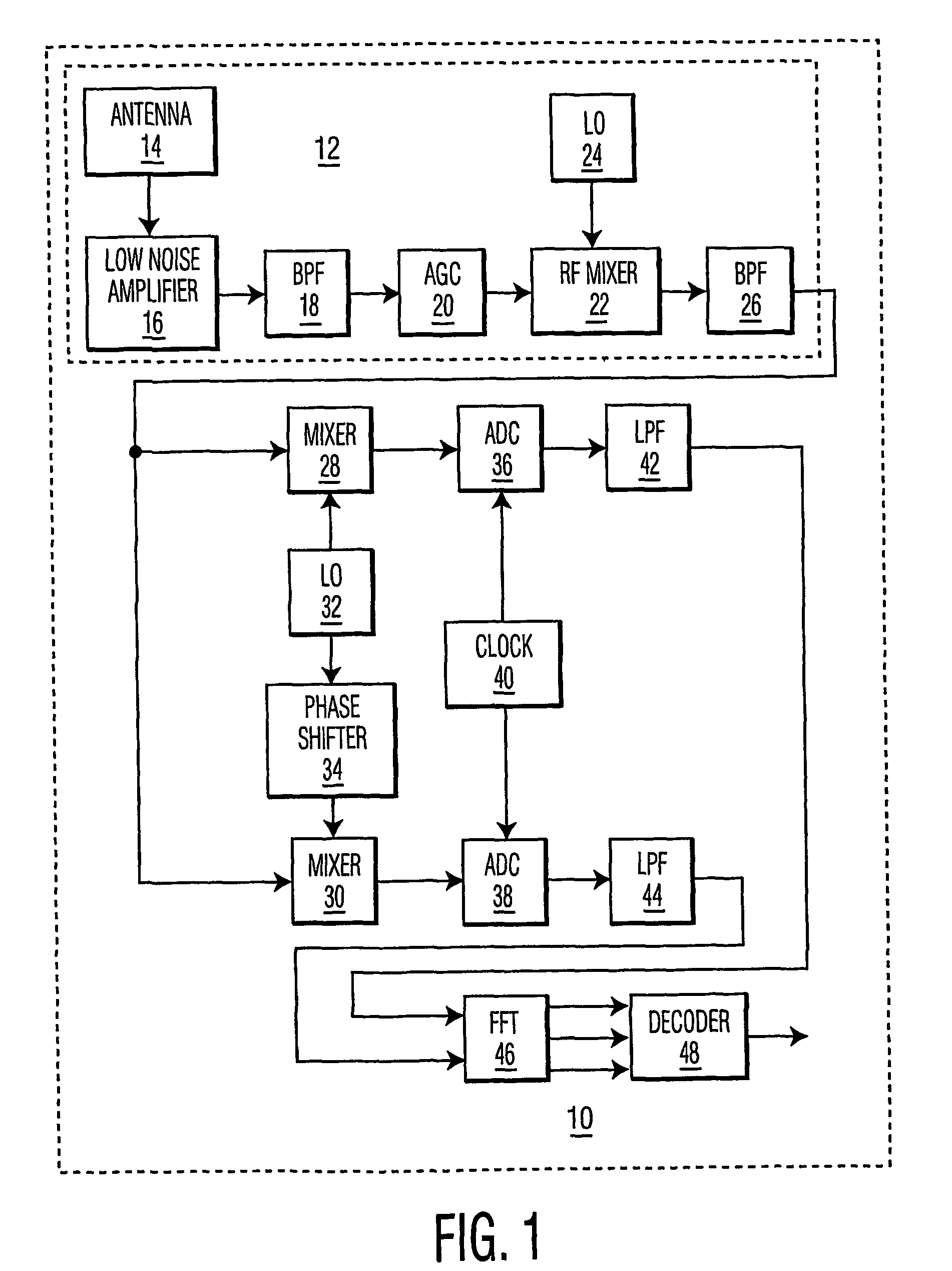
[0018]Referring to FIG. 1, the first element of a typical OFDM receiver 10 is an RF receiver 12. Many variations of RF receiver 12 exist and are well known in the art, but typically, RF receiver 12 includes an antenna 14, a low noise amplifier (LNA) 16, an RF bandpass filter 18, an automatic gain control (AGC) circuit 20, an RF mixer 22, an RF carrier frequency local oscillator 24, and an IF bandpass filter 26.

[0019]Through antenna 14, RF receiver 12 couples in the RF OFDM-modulated carrier after it passes through the channel. Then, by mixing it with a receiver carrier of frequency fcr generated by RF local oscillator 24, RF receiver 12 downconverts the RF OFDM-modulated carrier to obtain a received IF OFDM signal. The frequency difference between the receiver carrier and the transmitter carrier contributes to the carrier frequency offse...


PUM


Abstract

An Orthogonal Frequency Division Multiplexing (OFDM) receiver that employs N second-order phase-lock loops sharing a common integrator (where N is the number of pilots in the system). The N second order phase-lock loops track out independent pilot phase rotations to facilitate the constructive averaging of the pilots' phase information. At the same time, by sharing a common integrator, the OFDM receiver takes advantage of noise averaging over multiple pilots to obtain a cleaner frequency offset estimation. The OFDM receiver may also compensate for FFT window drift by calculating a phase difference between a selected pair of pilots and tracking the rate of change of the calculated phase difference over time. The calculated phase difference is used to control the position of an upstream FFT window after a predetermined phase difference threshold is exceeded. The tracked rate of change is used to continuously adjust the phase of downstream equalizer taps.

Description

[0001]This application claims the benefit, under 35 U.S.C. §365 of International Application PCT / US01 / 20054, filed Jun. 22, 2001, which was published in accordance with PCT Article 21(2) on Jan. 3, 2003 in English.BACKGROUND OF THE INVENTION[0002]The present invention relates to processing orthogonal frequency division multiplexed (OFDM) signals.[0003]A wireless LAN (WLAN) is a flexible data communications system implemented as an extension to, or as an alternative for, a wired LAN within a building or campus. Using electromagnetic waves, WLANs transmit and receive data over the air, minimizing the need for wired connections. Thus, WLANs combine data connectivity with user mobility, and, through simplified configuration, enable movable LANs. Some industries that have benefited from the productivity gains of using portable terminals (e.g., notebook computers) to transmit and receive real-time information are the digital home networking, health care, retail, manufacturing, and warehou...

Claims


Application Information

Patent Timeline
IPC IPC(8): H04L5/12H04L27/00H04J11/00H03L7/07H03L7/093H03L7/099H04L27/26
CPCH03L7/07H03L7/093H03L7/0991H04L27/2657H04L27/2662H04L27/2675H04L27/261H04L2027/0026H04L2027/0044H04L2027/0067H04J11/00
Inventor BELOTSERKOVSKY, MAXIM BORISOVICHDEMOULIN, VINCENTLITWIN, JR., LOUIS ROBERT
Owner INTERDIGITAL MADISON PATENT HLDG
Why Eureka
Try Eureka