Fabrication method for thermoelectric device

a technology of thermoelectric devices and fabrication methods, which is applied in the manufacture/treatment of thermoelectric devices, semiconductor devices, and thermoelectric devices, etc., can solve the problems of complex existing methods and the risk of degrading the performance of thermoelectric materials, and achieve the effect of simple methods of fabricating

Active Publication Date: 2012-06-12
SHANGHAI INST OF CERAMIC CHEM & TECH CHINESE ACAD OF SCI
View PDF20 Cites 5 Cited by
  • Summary
  • Abstract
  • Description
  • Claims
  • Application Information

AI Technical Summary

Benefits of technology

[0009]One purpose of the present disclosure is to provide a relatively simple method for fabricating a thermoelectric device. A method for fabricating thermoelectric device comprises (i) placing a first electrode in a die, (ii) forming a first interlayer on an upper surface of the first electrode, (iii) positioning a separating plate on an upper surface of the first interlayer to divide an inner space of the die into a plurality of cells, and depositing a first thermoelectric material on the first interlayer within a first fraction of the cells, and depositing a second thermoelectric material on the first interlayer within a second fraction of the cells, (iv) sintering the die contents; and (v) removing the separating plate after sintering to obtain a π shaped thermoelectric device.
[0023]The present disclosure embraces advantages of obtaining π shaped elements with one-step sintering and simplified procedures for obtaining π shaped elements, with minimal adverse impacts on performance of filled thermoelectric materials resulted from exposing filled thermoelectric materials to heat and pressure for a second time.

Problems solved by technology

However, the existing method is not only complex, but also inevitably exposes thermoelectric materials (such as filled skutterudite) again to heat and pressure with a risk of degrading the performance of thermoelectric materials.

Method used


Image

  • Fabrication method for thermoelectric device
  • Fabrication method for thermoelectric device

Examples


first embodiment

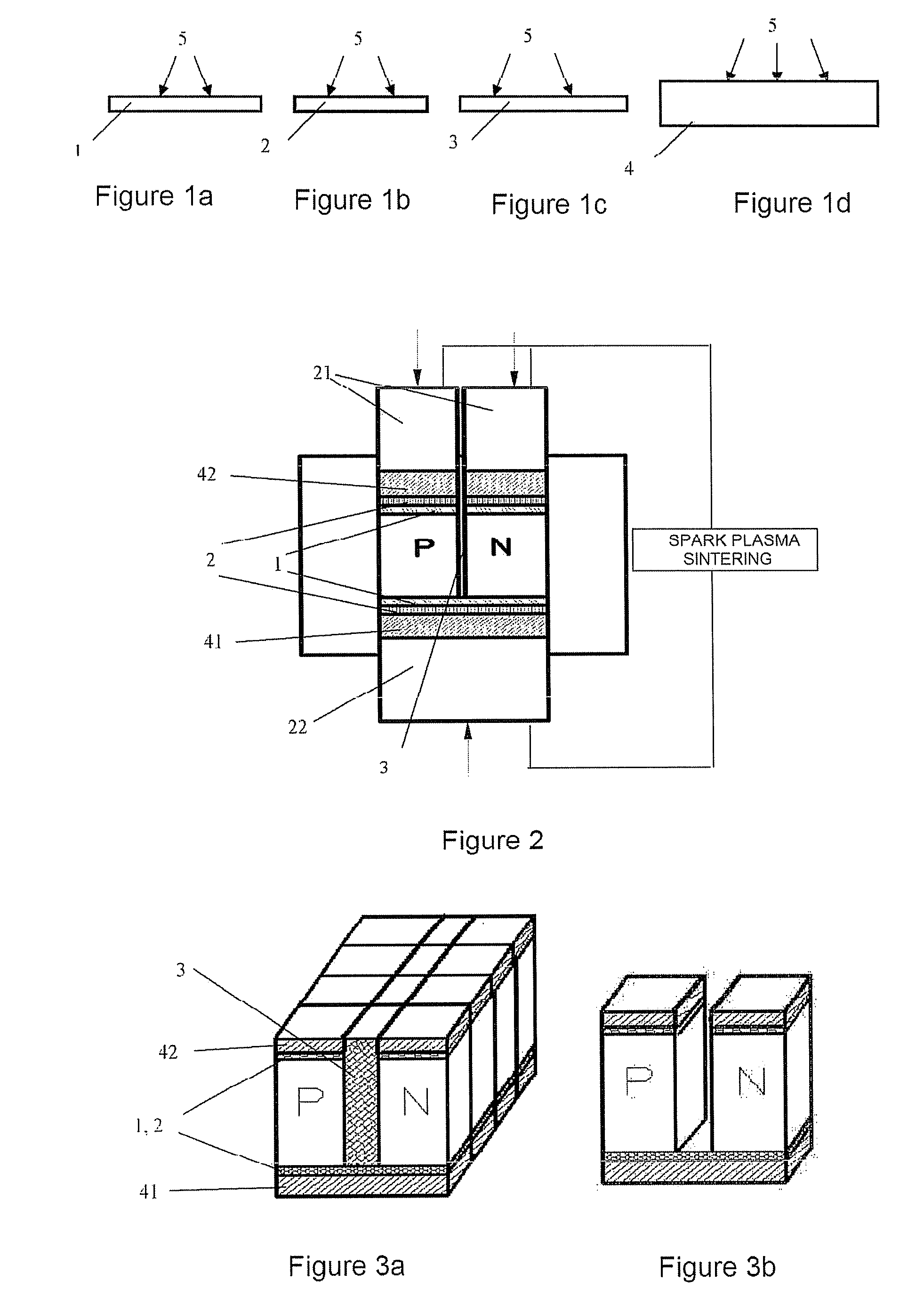
[0032]With reference to FIG. 1, a process of pretreatment 5 is performed. As shown in FIGS. 1a-1d, sand spraying or ultrasonic cleaning is performed on a barrier layer 1, a joint enhancement layer 2, a separating plate 3, and an electrode 4 to remove surface oxides or other impurities and to create roughness on the surface of electrode 4. Pretreatment is preferably performed with high purity quartz sand under spray pressure of 0.1-0.5 MPa for 30 sec to 3 min, and the time for ultrasonic cleaning may be 5-15 min.

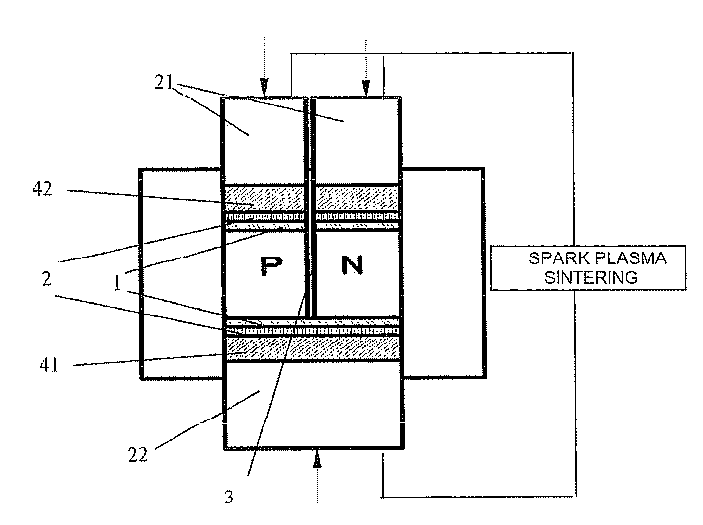
[0033]Next, referring to FIG. 2, a process of filling and sintering is performed. A hot end electrode 41, a joint enhancement layer 2a, and a barrier layer 1a are provided in a die sequentially. The joint enhancement layer 2a and the barrier layer 1a may be placed in a simple manner, or may adopt techniques such as plasma spraying, flame spraying, arc spraying or electroplating. Of course, there is no specific limitation on the placement, so that any placements known by those...

second embodiment

[0043]As compared to the first embodiment, the main distinction of the second embodiment is in the omission of a barrier layer, joint enhancement layer and cold end electrode prior to sintering. Consequently, the descriptions of same steps as those in the first embodiment are omitted below.

[0044]According to the second embodiment, during the filling process in the first embodiment, the barrier layer 1b, the joint enhancement layer 2b and the cold end electrode 42 are not inserted after adding p / n filled skutterudite powder, rather, the upper pressing head 21 is placed directly into contact with an upper surface of the thermoelectric powders, and a π shaped element without cold end electrode is obtained after sintering.

[0045]With respect to the π shaped element without sintering the cold end electrode, a barrier layer, a joint enhancement layer and a tin soldering layer may be fabricated on the cold side before welding the π shaped element to a copper-coated ceramic plate. And then, ...


PUM

PropertyMeasurementUnit
temperatureaaaaaaaaaa
pressureaaaaaaaaaa
thicknessaaaaaaaaaa

Abstract

A method for fabricating thermoelectric device is provided. The method comprises placing a first electrode in a die, forming a first interlayer on an upper surface of the first electrode; positioning a separating plate on an upper surface of the first interlayer to divide an inner space of the die into a plurality of cells, and depositing a first thermoelectric material on the first interlayer within a first fraction of the cells, and depositing a second thermoelectric material on the first interlayer within a second fraction of the cells, sintering the die contents, and removing the separating plate after sintering to obtain a π shaped thermoelectric device.

Description

PRIORITY[0001]This application claims priority to Chinese Patent Application number 200810207957.8, filed Dec. 26, 2008, titled “Method For Fabricating Thermoelectric Device.”FIELD OF THE INVENTION[0002]The present disclosure relates to a method for fabricating a thermoelectric device, and more specifically to a method for fabricating a thermoelectric device comprising a filled skutterudite.BACKGROUND[0003]The electricity generation by thermoelectricity is a technique utilizing Seebeck effects in semiconductor materials for realizing direct conversion from heat to electricity, which is characterized by long lifespan, high reliability, safe environment, etc. It has wide applications and potential social and economic effects in areas of electricity generation by photoelectricity and thermoelectricity, solar energy, and electricity generation by industrial waste heat. Improving the figure of merit of thermoelectric materials can be beneficial in improving energy conversion efficiency o...

Claims


Application Information

Patent Timeline
Patent Type & Authority Patents(United States)
IPC IPC(8): H01L21/04
CPCH01L35/32H01L35/34H10N10/17H10N10/01
Inventor CHEN, LIDONGBACKHAUS-RICOULT, MONIKAHE, LINLI, XIAOYAXIA, XUGUIZHAO, DEGANG
Owner SHANGHAI INST OF CERAMIC CHEM & TECH CHINESE ACAD OF SCI
Why Eureka
Try Eureka