Mirror for extreme ultra violet, manufacturing method for mirror for extreme ultra violet, and far ultraviolet light source device

a manufacturing method and ultra violet technology, applied in the direction of optical radiation measurement, electromagnetic radiation sensing, spectrometry/spectrophotometry/monochromator, etc., can solve the problems of heat melting, thin layer type spf can easily be damaged, and the efficiency and reliability of a thin layer type spf are difficult to achiev

Active Publication Date: 2012-06-12
GIGAPHOTON
View PDF21 Cites 15 Cited by
  • Summary
  • Abstract
  • Description
  • Claims
  • Application Information

AI Technical Summary

Problems solved by technology

The following problems are present with the prior art techniques described above.
The first such problem is that there are issues with the efficiency and the reliability of a thin layer type SPF.
Moreover, a thin layer type SPF can easily be damaged due to debris flying off and striking it.
Furthermore, when a thin layer type SPF absorbs radiation of wavelengths other than that of EUV radiation so that its temperature becomes elevated, it may melt due to heat, which is undesirable.
Thus, there are problems with a thin layer type SPF with regard to transmittivity to EUV radiation, and with regard to reliability and convenience of use.
The second problem is that, with the fourth prior art technique described above in which the composite layer is subjected to blazing processing, it is necessary to superimpose a total of 2000 or more of the Mo / Si multi layers.
The third problem is that, both with a thin layer type SPF and with an SPF which uses a reflective type diffraction lattice, the diffraction efficiency and the transmittivity for EUV radiation is low, and around 30% of the output of the EUV light source is consumed uselessly in the SPF.

Method used


Image

  • Mirror for extreme ultra violet, manufacturing method for mirror for extreme ultra violet, and far ultraviolet light source device
  • Mirror for extreme ultra violet, manufacturing method for mirror for extreme ultra violet, and far ultraviolet light source device
  • Mirror for extreme ultra violet, manufacturing method for mirror for extreme ultra violet, and far ultraviolet light source device

Examples


embodiment 1

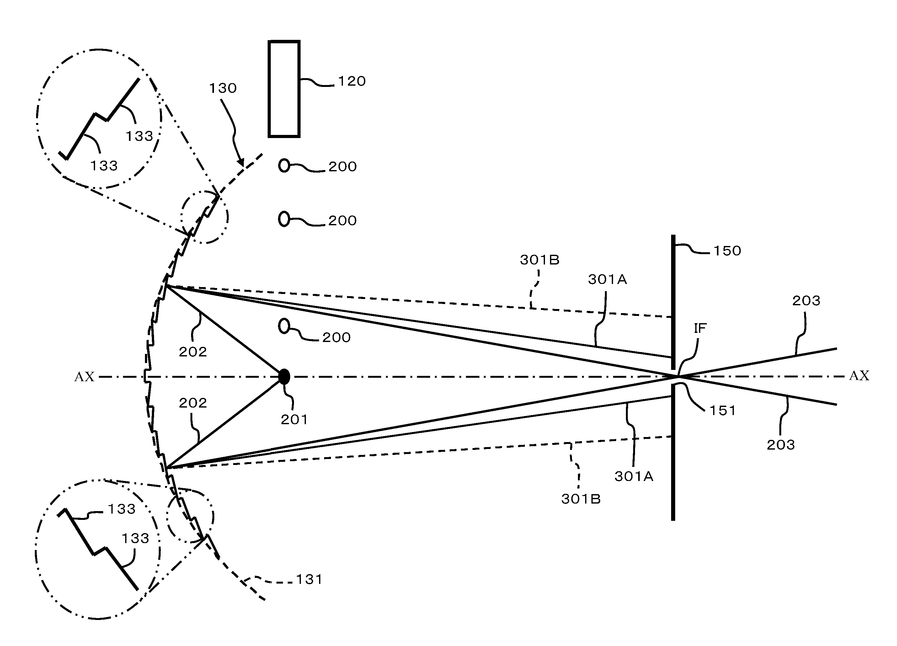
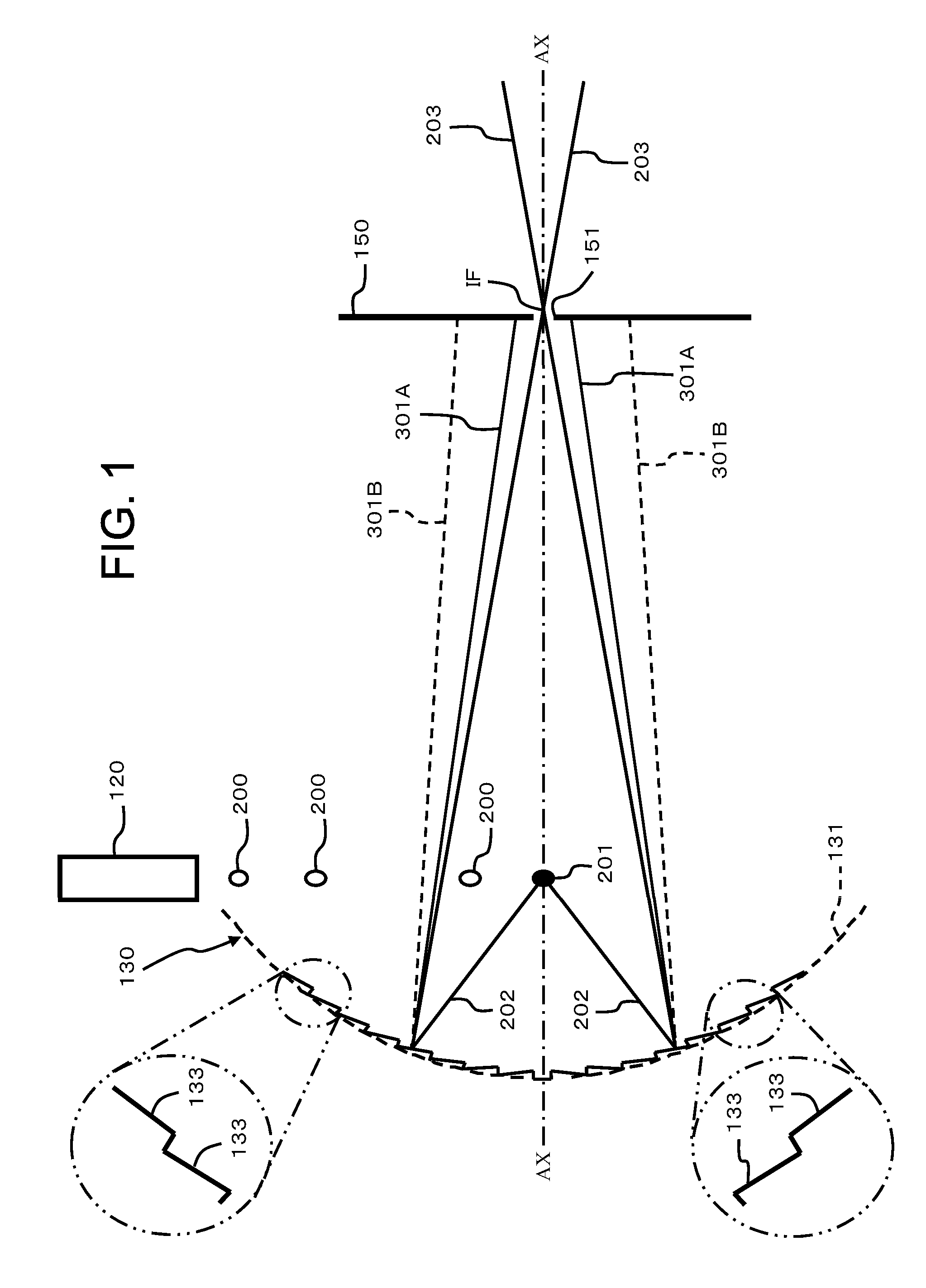
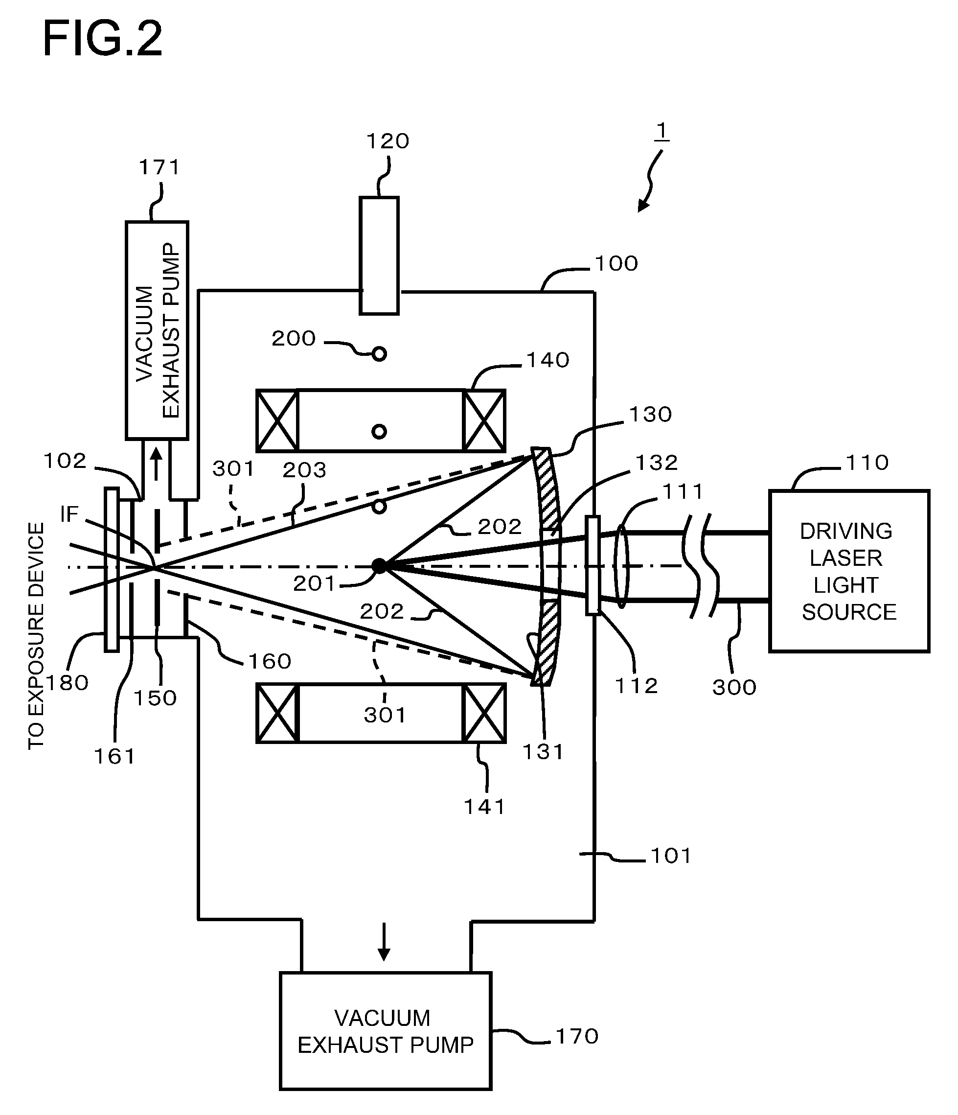
[0059]A first embodiment will now be explained on the basis of FIGS. 1 through 4. FIG. 1 is an explanatory figure showing a magnified view of an EUV collector mirror according to this first embodiment; FIG. 2 is an explanatory figure showing an EUV light source device which incorporates this EUV collector mirror 130; FIG. 3 is an explanatory sectional view showing a magnified view of blazed grooves of this EUV collector mirror 130; and FIG. 4 is a characteristic figure for the setting of Mo / Si pair layer thickness according to the angle of incidence of EUV radiation. First the structure of the EUV light source device 1 will be explained with reference to FIG. 2, and then the structure of the EUV collector mirror 130 will be explained with reference to FIG. 1 etc.

[0060]The EUV light source device 1 shown in FIG. 2 comprises, for example, a vacuum chamber 100, a driver laser light source 110, a target supply device 120, the EUV collector mirror 130, coils for magnetic field generation...

embodiment 2

[0124]A second embodiment of the present invention will now be explained on the basis of FIGS. 5 through 7. The second and third embodiments of the present invention which are described below correspond to variants of the first embodiment described above. Accordingly, the explanation thereof will focus upon the aspects in which these embodiments differ from the first embodiment. The aspects of difference between this second embodiment and the first embodiment are that the blazed grooves are angled in the opposite direction, and that, along with this difference, a dumper 105 is additionally provided.

[0125]FIG. 5 is an explanatory figure showing the EUV light source device 1A according to this second embodiment. A dumper 105 which is provided at a certain position upon the optical axis AX (refer to FIG. 6) absorbs the regularly reflected radiation 301A which has been deflected by the blazed grooves 133 and converts it to thermal energy. It may also be arranged for this dumper 105 to s...

embodiment 3

[0133]A third embodiment of the present invention will now be explained on the basis of FIGS. 8 and 9. In this third embodiment, the blazed grooves are formed in a somewhat different manner. FIG. 8 is a figure showing the EUV collector mirror 130 as seen from the front. The blazed grooves 133 may be formed as concentric circles, as shown in FIG. 8(a), or may be formed as parallel straight lines, as shown in FIG. 8(b).

[0134]If the blazed grooves 133 are formed as parallel straight lines as shown in FIG. 8(b), then it would also be possible, as shown in FIG. 9, to form the blazed grooves to extend in the same direction across the entire surface of the EUV collector mirror 130. Thus, with this third embodiment having the above structure, it is possible to obtain similar beneficial effects to those obtained in the case of the first embodiment.


PUM


Abstract

The EUV light source device eliminates radiation other than EUV radiation from the light which it emits, and supplies only the EUV radiation to an exposure device. A composite layer consisting of a plurality of Mo / Si pair layers is provided upon the front surface of an EUV collector mirror, and blazed grooves are formed in this composite layer. Radiation emitted from a plasma is incident upon this EUV collector mirror, and is reflected or diffracted. The reflected EUV radiation (including diffracted EUV) proceeds towards an intermediate focal point IF. The radiation of other wavelengths proceeds towards some position other than this focal point IF, because its reflection angle or diffraction angle is different. A SPF shield having an aperture portion is provided at the focal point IF. Accordingly, only the EUV radiation passes through the aperture portion and is supplied to the exposure device, while the other radiation is intercepted by the shield.

Description

CROSS REFERENCE TO RELATED APPLICATIONS[0001]The present application is based on and claims priority to Japanese Patent Application No. 2008-132479 and 2008-212787 filed on May 20, 2008, and Aug. 21, 2008, the contents of which are incorporated in their entirety herein by reference. This application is also related to U.S. application Ser. No. 12 / 469,176, entitled “SEMICONDUCTOR EXPOSURE DEVICE USING EXTREME ULTRA VIOLET RADIATION,” filed simultaneously on May 20, 2009 with the present application.BACKGROUND OF THE INVENTIONTechnical Field[0002]The present invention relates to a mirror for reflecting extreme ultra violet, to a method for manufacturing a mirror for extreme ultra violet, and to a far ultraviolet light source device which incorporates a mirror for extreme ultra violet.[0003]For example, a semiconductor chip may be created by projecting a mask upon which a circuit pattern is drawn, in reduced form, upon a wafer to which a resist has been applied, and by repeatedly perfo...

Claims


Application Information

Patent Timeline
Patent Type & Authority Patents(United States)
IPC IPC(8): G21K5/04G21K1/06
CPCG02B5/0891G02B5/1838G02B5/1857G03F7/70575G21K1/065G21K2201/064
Inventor MORIYA, MASATOWAKABAYASHI, OSAMUSOUMAGNE, GEORG
Owner GIGAPHOTON
Why Eureka
Try Eureka