Systems and methods for improving the performance of a photorefractive device

a technology of photorefractive devices and performance improvement, applied in the field of systems and methods for improving the performance of photorefractive devices, can solve the problems of long-term grating persistency and the disappearance of photorefractive grating almost immediately, and achieve the effect of prolonging the grating persistency of the photorefractive device comprising a polymer layer and holding it for a long tim

Active Publication Date: 2012-06-19
NITTO DENKO CORP +1
View PDF18 Cites 2 Cited by
  • Summary
  • Abstract
  • Description
  • Claims
  • Application Information

AI Technical Summary

Benefits of technology

[0011]One embodiment of the present disclosure provides a method for improving the performance of a photorefractive device comprising one or more transparent electrode layers and a photorefractive material. The method comprises interposing one or more polymer layers between the transparent electrode layer and the photorefractive material. In an embodiment, the peak diffraction efficiency bias of the photorefractive device after incorporating the one or more polymer layers in the photorefractive device is reduced when measured by using an approximately 532 nm laser beam, relative to a photorefractive device containing at least one transparent electrode layer and a photorefractive material without a polymer layer interposed there between.
[0012]In an embodiment of the method for improving the performance of a photorefractive device, the device comprises a first and a second electrode layers positioned adjacent the opposite sides of the photorefractive material, a first polymer layer interposed between the first electrode layer and the photorefractive material, and a second polymer layer interposed between the second electrode layer and the photorefractive material.
[0025]Surprisingly, the grating persistency of the photorefractive device comprising a polymer layer can be extended and held for long period of time, as compared to a photorefractive device without a polymer layer, when measured by an approximately 532 nm laser beam. Grating persistency values (time of grating drop to 1 / e of the initial value) that are surprisingly long have been measured in the photorefractive devices described herein. In an embodiment, the grating persistency of the photorefractive device is 1 minute or more when measured by an approximately 532 nm laser beam. In an embodiment, the grating persistency of the photorefractive device is 1 hour or more when measured by an approximately 532 nm laser beam. In an embodiment, the grating persistency of the photorefractive device is 2 hours or more when measured by an approximately 532 nm laser beam. In an embodiment, 90% of the grating remains even after 60 hours storage of the photorefractive device.

Problems solved by technology

While using a high biased voltage can result in a longer grating persistency, the use of a high voltage in the photorefractive material can cause the photorefractive grating to disappear almost immediately after stopping the applied biased voltage.

Method used


Image

  • Systems and methods for improving the performance of a photorefractive device
  • Systems and methods for improving the performance of a photorefractive device
  • Systems and methods for improving the performance of a photorefractive device

Examples


production example 1

Preparation of Copolymer by AIBN Radical Initiated Polymerization (TPD Acrylate / Chromophore Type 10:1)

[0116]The charge transport monomer N-[(meth)acroyloxypropylphenyl]-N,N′, N′-triphenyl-(1,1′-biphenyl)-4,4′-diamine (TPD acrylate) (about 43.34 g), and the non-linear-optical precursor monomer 5-[N-ethyl-N-4-formylphenyl]amino-pentyl acrylate (about 4.35 g), prepared as described above, were put into a three-necked flask. After toluene (about 400 mL) was added and purged by argon gas for about 1 hour, azoisobutylnitrile (about 118 mg) was added into this solution. Then, the solution was heated to about 65° C., while continuing to purge with argon gas.

[0117]After about 18 hrs polymerization, the polymer solution was diluted with toluene. The polymer was precipitated from the solution and added to methanol, then, the resulting polymer precipitate was collected and washed in diethyl ether and methanol. The white polymer powder was collected and dried. The yield of polymer was about 66%....

example 1

Preparation of Photorefractive Devices

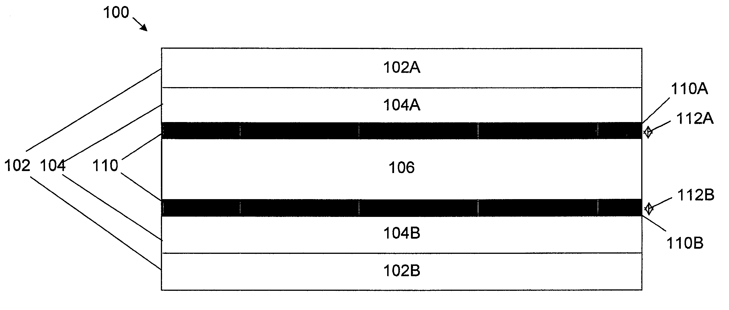
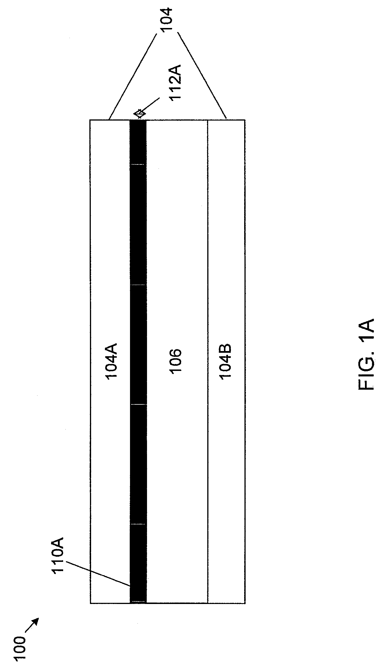
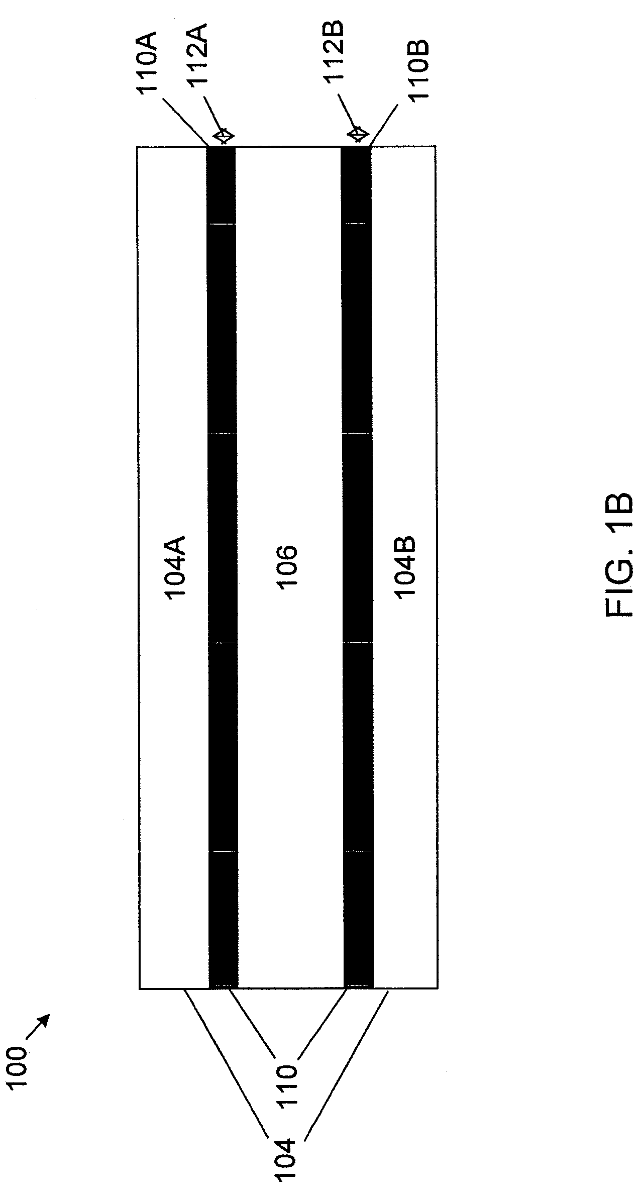
[0121]A photorefractive composition testing sample was prepared comprising two ITO-coated glass electrodes, two polymer layers, and a photorefractive layer. The components of the photorefractive composition were approximately as follows:

[0122]

(i) Matrix polymer (described in Production Example 1):50.0 wt %(ii) Prepared chromophore of 7FDCST30.0 wt %(iii) Ethyl carbazole plasticizer20.0 wt %

[0123]To prepare the photorefractive composition, the components listed above were dissolved with toluene and stirred overnight at room temperature. After removing the solvent by rotary evaporator and vacuum pump, the residue was scratched and gathered.

[0124]This powdery residue mixture, which is used to form the photorefractive layer, was put on a slide glass and melted at about 125° C. to make an approximately 200-300 μm thickness film, or pre-cake. A first electrode layer and a second electrode layer are positioned adjacent opposite sides of the photorefrac...

example 2

[0136]A photorefractive device was obtained in the same manner as in Example 1 except that the polymer layers were made from PMMA (polymethyl methacrylate). The grating persistency is measured by method (a) with applied bias on and reading beam on continuously.


PUM

PropertyMeasurementUnit
thicknessaaaaaaaaaa
thicknessaaaaaaaaaa
refractive indexaaaaaaaaaa

Abstract

A photorefractive device (100) and method of manufacture are disclosed. The device (100) comprises a layered structure in which one or more polymer layers (110) are interposed between a photorefractive material (106) and at least one transparent electrode layer (104). The layered structure is further interposed between a plurality of substrates (102). When a bias is applied to the device (100), the device (100) exhibits an increase in signal efficiency of approximately three to four times that of similar, but non-buffered, devices. Concurrently, the device (100) of the present disclosure utilizes approximately half the biased voltage, advantageously resulting in a longer device lifetime.

Description

CROSS REFERENCE TO RELATED APPLICATIONS[0001]This application is a U.S. National Phase of PCT International Application Number PCT / US20085 / 050056, filed on Jan. 2, 2008, designating the United States of America and published in the English language, which claims priority to U.S. Provisional Patent Application No. 60 / 886,869, filed on Jan. 26, 2007. The disclosures of the above-described applications are hereby incorporated by reference in their entirety.BACKGROUND OF THE INVENTION[0002]1. Field of the Invention[0003]The invention relates to methods for improving the properties of photorefractive materials and to utilizing multiple layers to improve the performance, particularly the grating or image persistency of photorefractive materials.[0004]2. Description of the Related Art[0005]Photorefractivity is a phenomenon in which the refractive index of a material can be altered by changing the electric field within the material, such as by laser beam irradiation. The change of the refra...

Claims


Application Information

Patent Timeline
Patent Type & Authority Patents(United States)
IPC IPC(8): G02F1/29
CPCG02F1/3501G02F1/397G03H2001/2655G03H2260/36G03H2260/54
Inventor YAMAMOTO, MICHIHARUWANG, PENGPEYGHAMBARIAN, NASSERLIN, WEIPING
Owner NITTO DENKO CORP
Why Eureka
Try Eureka