
Anti-reflection film forming material, and method for forming resist pattern using the same

a technology of anti-reflection film and resist pattern, which is applied in the direction of photosensitive materials, instruments, photomechanical equipment, etc., can solve the problems of difficulty in aligning the mask, increasing the number of operation steps accordingly, and the method cannot always be applied to any substrate processing. , to achieve the effect of superior storage stability

Active Publication Date: 2012-07-10
TOKYO OHKA KOGYO CO LTD
View PDF8 Cites 0 Cited by
  • Summary
  • Abstract
  • Description
  • Claims
  • Application Information

AI Technical Summary

Benefits of technology

The material achieves improved storage stability and optical characteristics comparable to PFOS-based films without the regulatory and environmental concerns, enhancing the accuracy of resist patterns and simplifying the manufacturing process.

Problems solved by technology

However, in the method in which an anti-reflection film is formed on a substrate, mask alignment carried out using a light having the same wavelength as that of the exposure light may be disadvantageous since the detection signal of the mask alignment is attenuated by the anti-reflection film, thereby leading to difficulties in aligning the mask.
Thus, the number of operation steps increases accordingly; therefore, the method cannot always be applied to any substrate processing.
This substance is problematic in handling since it is a designated chemical substance in Japan, and also is subject to Significant New Use Rule (SNUR) that is a rule related to ecological effects in USA.
Specifically, the substance relevant to SNUR can involve taking risks which may impair the health or environment, therefore, wearing of protective equipments in the workplace, and notice, education, training and the like for employees about hazardous properties are required.

Method used


Image

  • Anti-reflection film forming material, and method for forming resist pattern using the same
  • Anti-reflection film forming material, and method for forming resist pattern using the same
  • Anti-reflection film forming material, and method for forming resist pattern using the same

Examples


example 1

[0085]To 97.2 parts by mass of pure water were added 0.84 parts by mass of a vinylpyrrolidone-vinyl acetate copolymer (vinylpyrrolidone constituent unit: vinyl acetate constituent unit=7:3 (molar ratio), mass average molecular weight: 10,000) as a water soluble resin (a), 1.68 parts by mass of a compound (m=6, manufactured by Omnova Solutions, Inc.) represented by the above formula (1d′) as a fluorine compound (b), and 0.05 parts by mass of “Surfinol 420” (manufactured by Air Products and Chemicals, Inc.) as a nonionic surfactant, respectively. To this mixture was added 3-amino-1,2-propanediol, and the pH was adjusted to 2.0, whereby an anti-reflection film forming material was obtained.

example 2

[0086]An anti-reflection film forming material was obtained in a similar manner to Example 1 except that monoethanolamine was used in place of 3-amino-1,2-propanediol.

example 3

[0087]An anti-reflection film forming material was obtained in a similar manner to Example 1 except that a vinyl alcohol-vinyl acetate copolymer (vinyl alcohol constituent unit: vinyl acetate constituent unit=7:3 (molar ratio), mass average molecular weight: 30,000) was used as the water soluble resin (a).


PUM

PropertyMeasurementUnit
thicknessaaaaaaaaaa
refractive indexaaaaaaaaaa
thicknessaaaaaaaaaa

Abstract

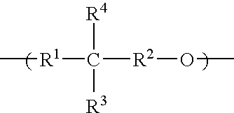
The anti-reflection film forming material according to the present invention includes (a) a water soluble resin having a vinyl acetate constituent unit, and (b) a compound having a constituent unit represented by the following general formula.Wherein, R1 and R2 represent a direct bond or a methylene chain; R3 and R4 represent a hydrogen atom, an alkyl group having 1 to 10 carbon atoms, or a group represented by —(CH2)n—O—R5—R6; and at least one of R3 and R4 is a group represented by —(CH2)n—O—R5—R6, wherein: R5 represents a direct bond or an alkylene chain having 1 to 10 carbon atoms which may be interrupted with —O—; R6 represents an alkyl group having 1 to 10 carbon atoms in which a portion or all hydrogen atoms are substituted with a fluorine atom; and n represents an integer of 0 to 10. Wherein, the total number of carbon atoms present in R1 and R2 is 1 or 2.

Description

[0001]This application is based on and claims the benefit of priority from Japanese Patent Application No. 2008-097146, filed on 3 Apr. 2008, the content of which is incorporated herein by reference.BACKGROUND OF THE INVENTION[0002]1. Field of the Invention[0003]The present invention relates to an anti-reflection film forming material for forming an anti-reflection film to be provided on a resist film, and a method for forming a resist pattern using the anti-reflection film forming material.[0004]2. Related Art[0005]Semiconductor wiring substrates are generally formed by laminating a dielectric layer (insulation layer) on a silicon wafer, or the like. A patterned conductive layer (i.e., a wiring layer) is then formed in the dielectric layer to form a semiconductor wiring structure.[0006]The formation of the wiring layer is carried out as follows. First, a conductive layer is formed on a dielectric layer uniformly, and a resist film is formed on this conductive layer. A resist patter...

Claims


Application Information

Patent Timeline
Patent Type & Authority Patents(United States)
IPC IPC(8): H01L21/027G03F7/30G03F7/11
CPCC09D139/06G03F7/091C08K5/17C08K5/175C08K5/19Y10S438/952
Inventor SHIRAI, YURIKOHIROSAKI, TAKAKOMASUJIMA, MASAHIROSAWANO, ATSUSHIKOSHIYAMA, JUN
Owner TOKYO OHKA KOGYO CO LTD
Learn More