Process for producing liquid hydrocarbon by pyrolysis of biomass in presence of hydrogen from a carbon-free energy source

a technology of carbon-free energy source and biomass, which is applied in the field of synthesis of liquid hydrocarbon, can solve the problems of not being suitable for replacement of diesel or gasoline, bio-oil formed directly from fast pyrolysis, and not being able to easily blend with petroleum products, etc., and achieves stable bio-oil and high energy content. , the effect of building on a relatively small scal

Active Publication Date: 2012-07-10
PURDUE RES FOUND INC
View PDF12 Cites 48 Cited by
  • Summary
  • Abstract
  • Description
  • Claims
  • Application Information

AI Technical Summary

Benefits of technology

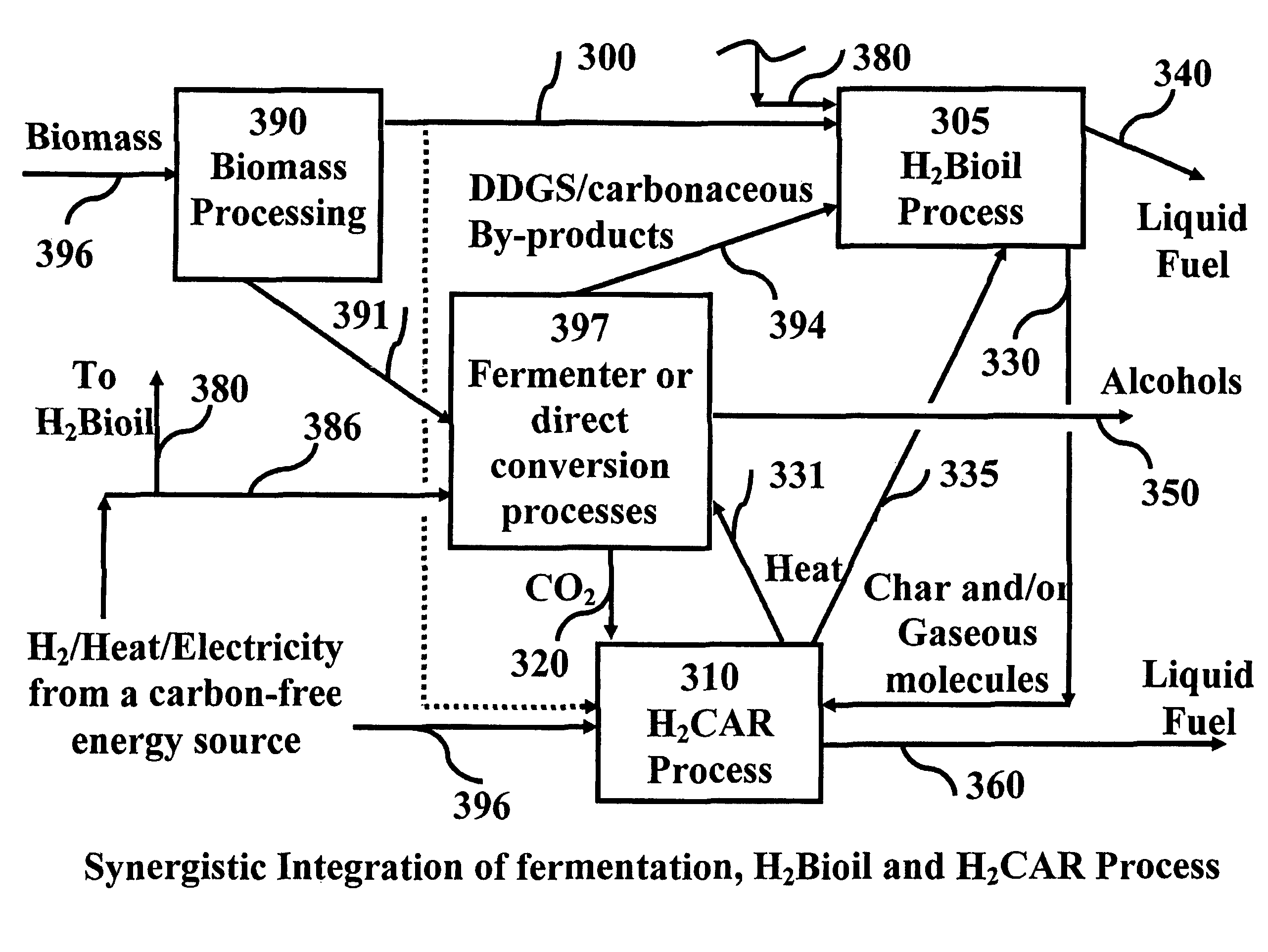
[0007]Recently the Applicants discovered a thermo-chemical process where hydrogen from a carbon-free energy source is used in conjunction with the gasification of the biomass or a suitable carbon containing moiety [4, 5]. This preferably suppresses the formation of CO2 and adjusts the ratio of H2 to CO desired for the subsequent conversion of the syngas to a liquid fuel. An example of a subsequent conversion process is the use of a FT reactor to produce diesel. The process was nicknamed H2CAR by the Applicants. The H2CAR process minimizes / eliminates the release of carbon to atmosphere as CO2 during the biomass to liquid fuel conversion process and thereby maximizes the yield of liquid fuel.
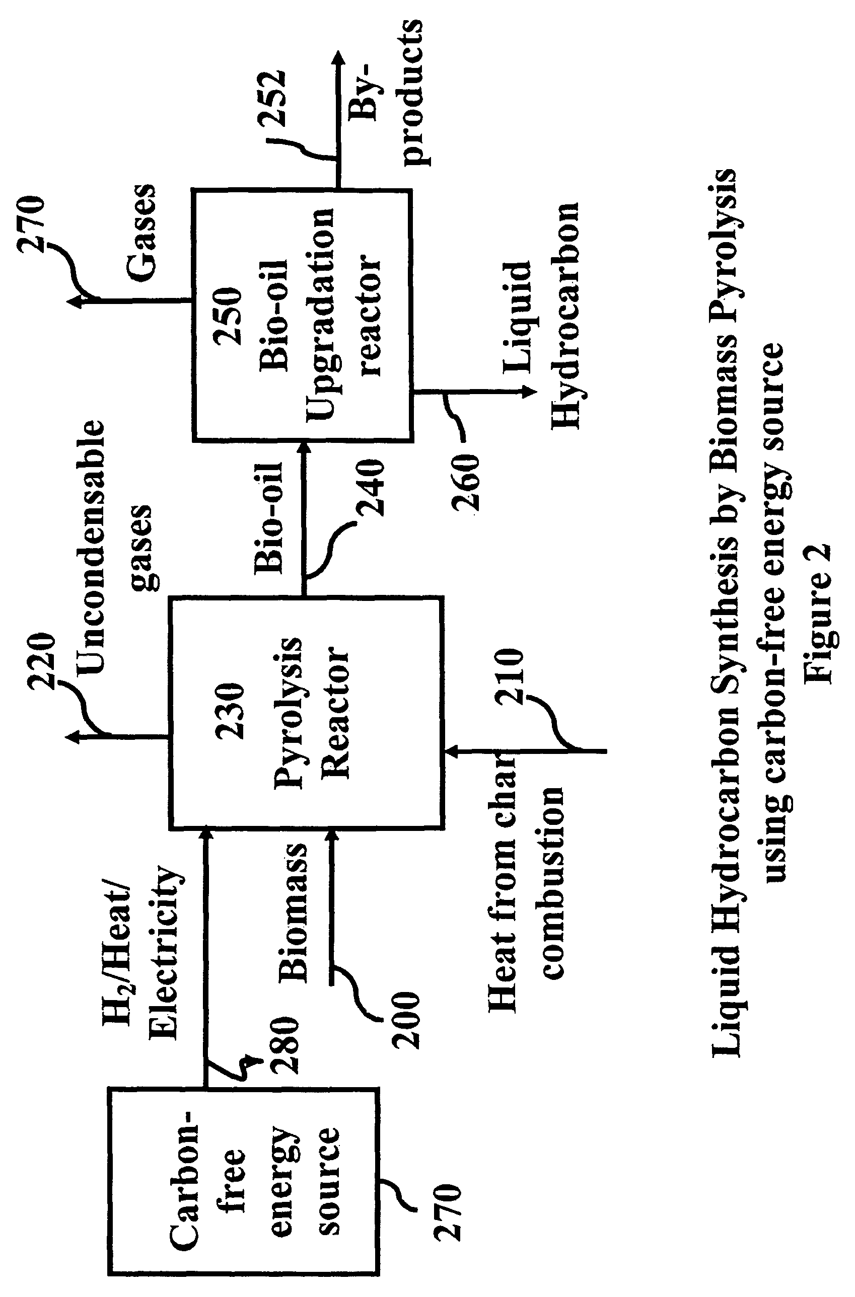
[0014]In at least one embodiment of the present invention, a biomass conversion process is provided that is efficient, can be built on a relatively small scale and provides stable bio-oil with high energy content that can be either directly used by the transportation sector or requires minimal additional processing. In one aspect, the present invention uses H2 from a carbon-free energy source during pyrolysis of biomass to increase the ‘Sun to Fuel’ power recovery per unit land area. This increase in solar energy utilization will decrease the land area required to produce a given quantity of liquid. Processes reported in the literature on the synthesis of liquid hydrocarbon fuels from biomass are not able to meet the need for the entire US transportation sector because biomass can only store 5 W / m2 of 1000 W / m2 available from Sun at a typical biomass growth efficiency of about 0.52% after accounting for agricultural energy input. In one embodiment, the utilization of power available from the Sun per unit land area is significantly increased as compared to the prior art processes. Power available from Sun can be stored at ˜70 W / m2 in H2 via solar thermal electric or Photovoltaic (PV). Combining biomass pyrolysis and carbon-free H2 for liquid fuel production preferably increases the power utilization from the Sun significantly while producing bio-oil with a relatively higher energy density.

Problems solved by technology

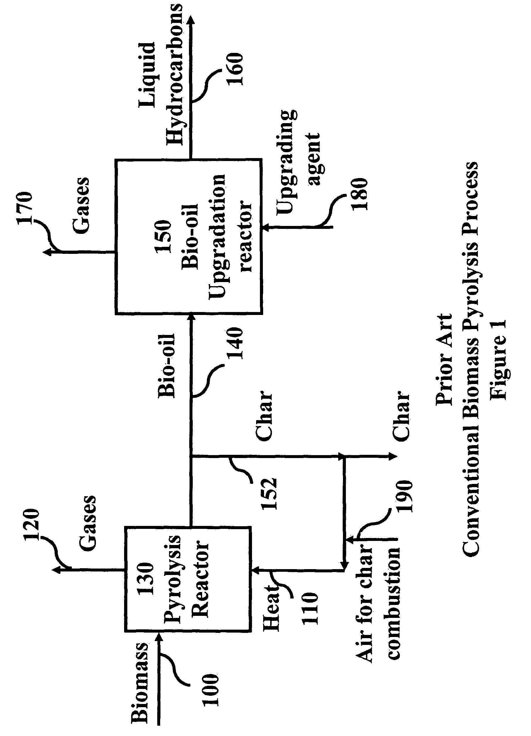
Bio-oil formed directly from fast pyrolysis, however, may not be suitable for replacement of diesel or gasoline due to its low heating value, solid content, high viscosity, chemical instability etc [7].
Furthermore, such bio-oils do not easily blend with petroleum products.
Zeolite upgrading is feasible at atmospheric pressure and no H2 is required decreasing the operating cost, however, poor hydrocarbon yields 160 and high yields of coke limit the usefulness of this process [7].

Method used


Image

  • Process for producing liquid hydrocarbon by pyrolysis of biomass in presence of hydrogen from a carbon-free energy source
  • Process for producing liquid hydrocarbon by pyrolysis of biomass in presence of hydrogen from a carbon-free energy source
  • Process for producing liquid hydrocarbon by pyrolysis of biomass in presence of hydrogen from a carbon-free energy source

Examples


example 1

[0042]To further illustrate the benefits of at least one embodiment of the present invention as compared to the prior art, the power utilization per m2 of land area is depicted using various processes based on a solar insolation of 1000 W / m2, which is a normalized value used for comparative purposes. The Annualized Energy Efficiency (AEE) based on the energy coming from Sun [4] and for a biomass growth rate of approximately 1.86 kg / m2 / yr is calculated to be approximately 0.52% (Biomass assumed here is corn grown in US, annual productivity of which is approximately 9296 kg / ha [3]. Assuming a harvest index of approximately 0.5 [14], net biomass growth rate becomes approximately 1.86 kg / m2 / yr). Based on approximately 1000 W / m2 available from the Sun, approximately 5.2 W / m2 is stored in the form of biomass. Hill et al. reported 6.39 MJ / l ethanol as the agricultural energy input required to obtain this corn growth rate which translates to approximately 0.2 W / m2 [3]. Accordingly, the net ...

example 2

[0044]In an embodiment in accordance with the present invention, the total incident solar power is split to grow biomass (approximately 979 W) and produce H2 by an electrolytic route (approximately 21 W). After accounting for approximately 15% efficiency of solar-thermal electric or PV and approximately 50.7% conversion efficiency of electricity to H2, approximately 1.6 W / m2 is available as H2 for utilization in the H2Bioil process. Similar efficiency for the hydropyrolysis are used in the H2Bioil process (approximately 82%) of FIG. 4 where the power utilization for the H2Bioil process is approximately 5.3 W / m2, which is much higher than the other processes. The approach of directly utilizing H2 from a carbon-free energy source increases the ‘Sun to Fuel’ power recovery as shown in FIG. 5. This illustrates a beneficial effect of injecting H2 from a carbon-free energy source during the H2Bioil process. It is worth noting that compared to the conventional pyrolysis process, the H2Bioi...


PUM

PropertyMeasurementUnit
temperatureaaaaaaaaaa
energy densityaaaaaaaaaa

Abstract

In at least one embodiment of the present invention, a method for producing liquid hydrocarbons from biomass is provided. The method comprises pyrolizing the biomass with hydrogen (H2) to form bio-oil. The bio-oil comprises alkanes, alkenes, alcohols, aldehydes, ketones, aromatics, hydrocarbons or mixtures thereof. The H2 is formed from a carbon-free energy source.

Description

CROSS-REFERENCE TO RELATED APPLICATIONS[0001]This application claims priority to U.S. Provisional Application No. 60 / 968,194, filed on Aug. 27, 2007, the entire contents of which are incorporated herein by reference.TECHNICAL FIELD[0002]The present invention relates generally to the synthesis of liquid hydrocarbon, and in particular to the synthesis of liquid hydrocarbon by pyrolysis of biomass in presence of hydrogen (H2) from a carbon-free energy source.BACKGROUND OF THE INVENTION[0003]An important challenge facing society today is securing a sustainable fuel supply for the transportation sector. The transportation sector currently relies almost exclusively on liquid hydrocarbons as its energy source. The high energy density of gasoline, 8.88 kWh / liter, far exceeds that of proposed replacements H2, 1.32 kWh / liter at 680 atm [1], or batteries, 175 Wh / kg [2]. Furthermore, the liquid hydrocarbon fuel distribution infrastructure is efficient and already in place.[0004]Production of li...

Claims


Application Information

Patent Timeline
Patent Type & Authority Patents(United States)
IPC IPC(8): C07C1/00C10L3/00C12M1/00
CPCC01B3/042C01B3/068C10G1/00C10G1/002C10G1/06C10G1/08C10G1/086C12P5/00C10G3/46C10G3/49C10G3/52Y02E60/364C10G2300/1014Y02P30/20Y02P20/133Y02E60/36
Inventor AGRAWAL, RAKESHAGRAWAL, MANJUSINGH, NAVNEET R.
Owner PURDUE RES FOUND INC
Why Eureka
Try Eureka