Restoration process for porosity defects in metal cast products

a metal cast and porosity technology, applied in the field of metal cast product porosity defect restoration process, can solve the problems of failure of many parts, surface porosity defects in sand casting, and surface porosity defects in cast parts, so as to reduce the number of parts. the effect of porosity and small porosity

Active Publication Date: 2012-07-17
BRUNSWICK CORPORATION
View PDF21 Cites 10 Cited by
  • Summary
  • Abstract
  • Description
  • Claims
  • Application Information

AI Technical Summary

Benefits of technology

[0003]Surprisingly, it has been found that the surface porosity problem may be remedied by a highly efficient restoration process that eliminates surface porosity on an exposed surface. The restoration process of the present application allows for the restoration of parts that would otherwise be scrapped creating a strong economic advantage. The process of the present application is also superior to the restoration processes that currently defines the state of the art.
[0006]Another drawback of the putty solution is that manufacturing restrictions only allow three polymer matrix repair putty patches per engine block. The putty solution further complicates plant productivity efficiencies insofar as the putty requires curing for 24 hours before final finishing of the engine block surface. Therefore, a combination of the high pressure die cast process along with the putty solution requires a significant queue for an engine block line that requires continuous seven day production to keep up with a five day demand.
[0007]An additional secondary operation utilized in the current state of the art is the use of a metal soldering patch in replacement of the polymer matrix repair putty. This “soldering solution” requires the application of a low melting point alloy on top of the identified surface porosity. Conceptually, this solution has three main advantages: 1) the patch would not be visible after cleanup; 2) it could be utilized on more than three repair sites per engine block head deck; and 3) it would not require any curing time between application and finishing, thus eliminating the need for a queue of blocks.
[0009]As a result of the concerns about the putty solution as well as the soldering solution, alternative solutions have been explored. Surprisingly, the restoration process of the present application captures the three noted advantages of the soldering solution without having a bonding problem, a Galvanic corrosion problem, nor a heat input problem. This novel restoration process efficiently and economically restores for use cast part surfaces having surface porosity defects. The restoration process of the present application eliminates surface porosity defects using a spray filler. In one embodiment, the spray filler is significantly different in composition from the substrate material. In other embodiments, the filler and substrate material are the same or similar. Further, with the present application, there is no need to make smaller porosity defects “bigger” for applying the repair spray nor is there a limit to the number or size of porosity defects that may be repaired. Further, there is no heat distortion imparted to the engine blocks nor do Galvonic corrosion concerns exist.
[0010]As a result of these advantages, there is significantly less scrapping of cast products, resulting in a much more efficient production process. The restoration process of the present application also does not require any waiting or curing time between the application of the restoration process and the final finishing of the block. Thus, no production queue is needed and level loading of the blocks may be planned through the production and machining process, further increasing the efficiency of production compared to the putty solution or the soldering solution. Finally, the aesthetic problem associated with the putty solution is eliminated as repaired porosity defects are not visible after clean up.
[0012]Crank pin journals are defined as the area where a connecting rod attaches to a crankshaft in an engine. The use of metal spray enhances the durability of crank pen journals to wear by building up the area of attachment. Similarly, the aircraft industry has used metal spraying of complete cylinder bores to produce a coating that reduces wear problems.

Problems solved by technology

However, the lost foam casting process sometimes results in surface porosities on cast parts.
Surface porosity defects are also present in sand casting, die casting and permanent mold casting processes.
This porosity causes failures for many parts, particularly for parts that require sealing on a surface containing such porosity, because the porosity causes leaks around the seals.
As a result, many cast products are rejected and scrapped for quality considerations.
This approach to the repair of surface porosities is termed the “putty solution.” The disadvantage of the use of polymer matrix repair putty is that it may not be used on surface porosity smaller than 0.080 inches in diameter.
Still, the solution is imperfect as the drilling increases the surface porosity before the Devcon® repair putty is able to effectively fill the porosity with a sufficient bonding patch.
The drilling step also requires the use of additional resources making the process less efficient.
Additionally, the patch is not aesthetically pleasing to consumers and may convey a message that the blocks are substandard.
Another drawback of the putty solution is that manufacturing restrictions only allow three polymer matrix repair putty patches per engine block.
The putty solution further complicates plant productivity efficiencies insofar as the putty requires curing for 24 hours before final finishing of the engine block surface.
Therefore, a combination of the high pressure die cast process along with the putty solution requires a significant queue for an engine block line that requires continuous seven day production to keep up with a five day demand.
However, the soldering solution has a major drawback in that a Galvanic couple exists between the dissimilar base metal and soldering patch.
The Galvanic couple is problematic when it comes into contact with salt water, because salt water corrodes the soldering patch.
As many of the products produced by the Applicant are for marine applications, and specifically for salt water marine applications, such a problem is quite disadvantageous.
Further, the soldering solution requires a heat input to the engine block surface which may result in heat distortion defects, discoloration, and overaging of the precipitation strengthened cast product.
However, neither of the above stated uses of metal spraying have been contemplated for the restoration of surface porosity defects.

Method used


Image

  • Restoration process for porosity defects in metal cast products
  • Restoration process for porosity defects in metal cast products
  • Restoration process for porosity defects in metal cast products

Examples


Embodiment Construction

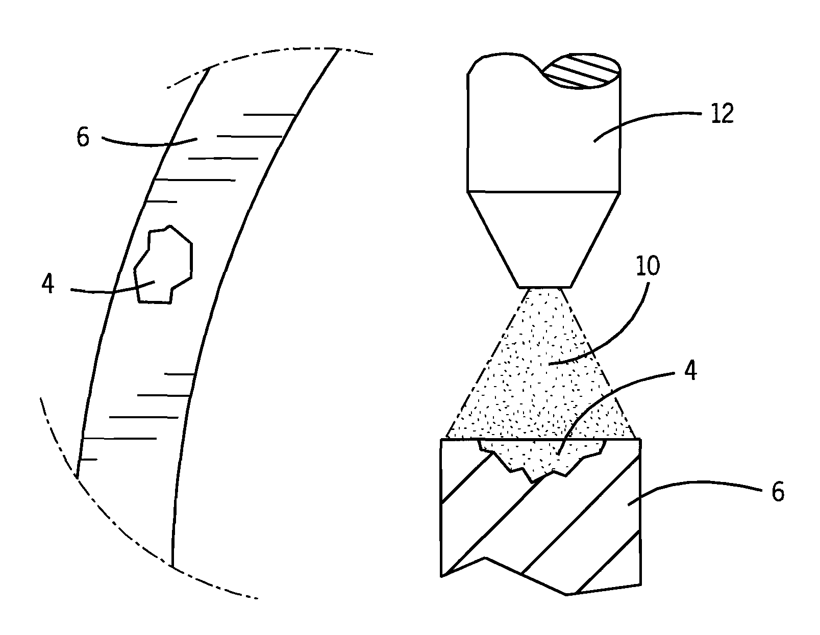
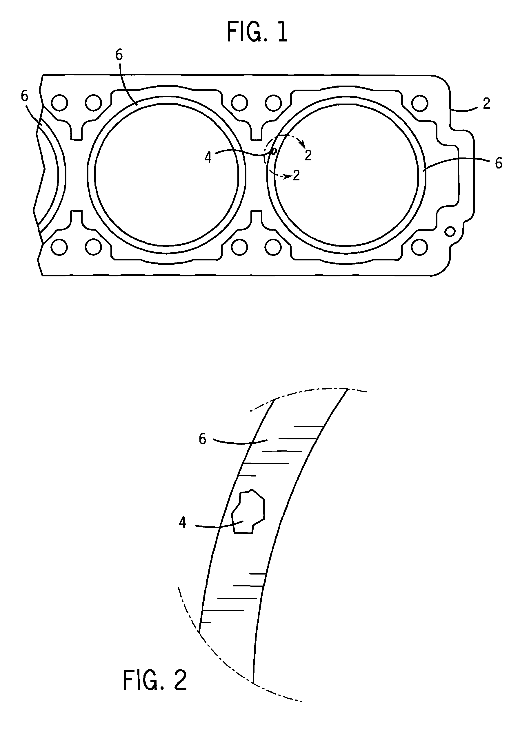
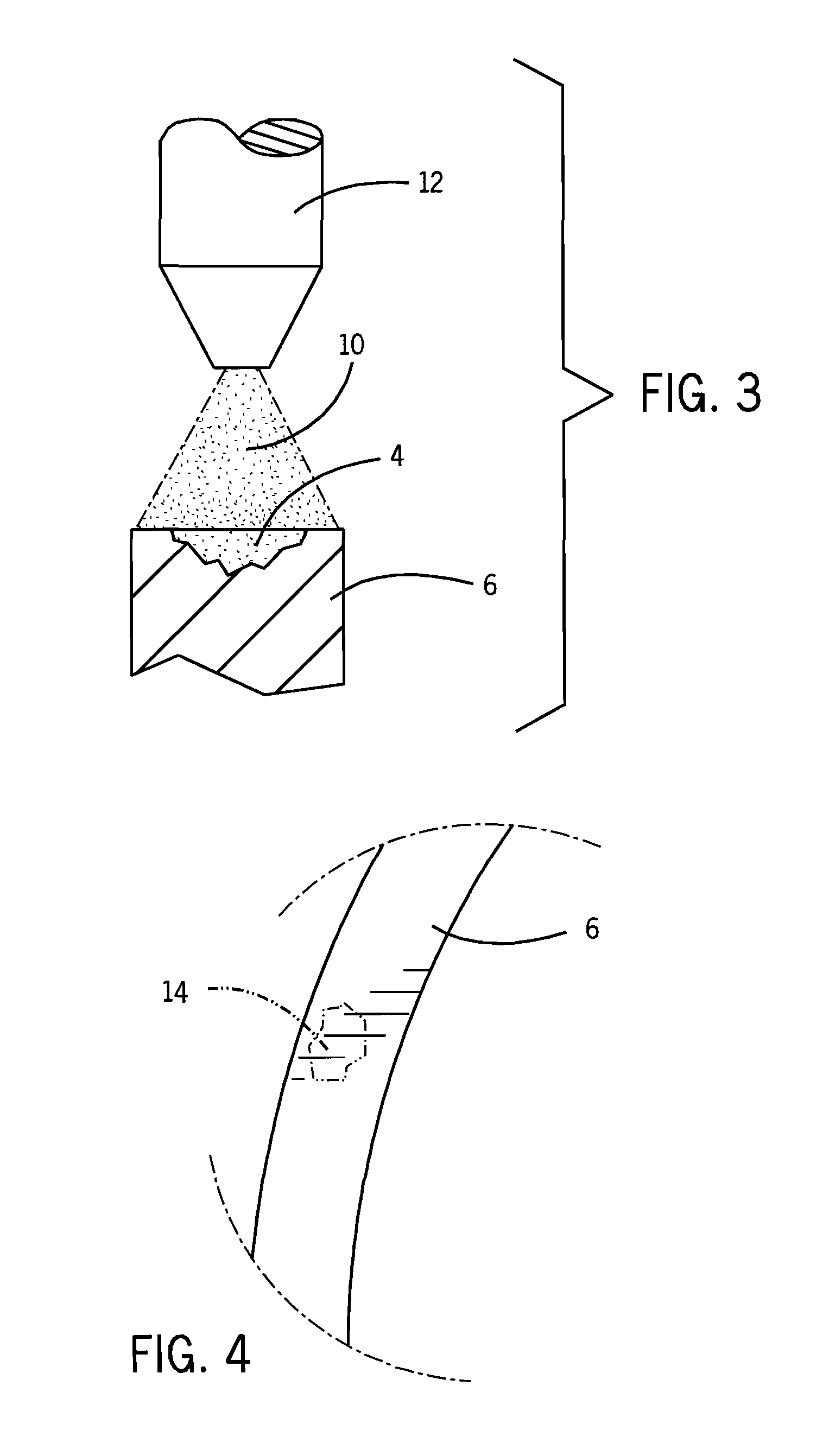
[0022]A restoration process for repairing surface porosity defects on a surface of a cast component or on a sealing surface is described below. Referring to FIG. 1, a component 2 may be cast using the lost foam casting method. The lost foam method is used to cast a variety of complex shapes, such as a hydraulic manifold casting, but sometimes yields a number of surface porosity defects in the final cast article. However, other casting processes also yield surface porosity defects, including die casting, sand casting and permanent mold casting; therefore, the present application may be used for any type of cast product.

[0023]Surface porosity defects may be revealed when the component 2 is machined subsequent to casting. Surface porosity defects 4 often result from the entrapment of air at the molten metal front during the lost foam casting process. However, as mentioned, surface porosity defects may also be present in other casting processes resulting from e.g., precipitation of hydr...


PUM

PropertyMeasurementUnit
diameteraaaaaaaaaa
diameteraaaaaaaaaa
porosityaaaaaaaaaa

Abstract

A restoration process for restoring surface porosity defects on a component surface. The areas of a component surface having surface porosity defects are identified for restoration. The restoration surface is subsequently sprayed with a restoration spray to restore the surface porosity defects. The component surface is then finished to create a final component substantially free of surface porosity.

Description

CROSS-REFERENCE TO RELATED APPLICATION[0001]This application is a continuation-in-part of U.S. patent application Ser. No. 11 / 638,544, filed Dec. 13, 2006, which is a continuation of U.S. patent application Ser. No. 10 / 358,480, filed Feb. 5, 2003, now U.S. Pat. No. 7,188,416.BACKGROUND AND SUMMARY OF THE INVENTION[0002]Lost foam casting of products is well known in the casting industry. However, the lost foam casting process sometimes results in surface porosities on cast parts. Surface porosity defects are also present in sand casting, die casting and permanent mold casting processes. This porosity causes failures for many parts, particularly for parts that require sealing on a surface containing such porosity, because the porosity causes leaks around the seals. As a result, many cast products are rejected and scrapped for quality considerations.[0003]Surprisingly, it has been found that the surface porosity problem may be remedied by a highly efficient restoration process that eli...

Claims


Application Information

Patent Timeline
Patent Type & Authority Patents(United States)
IPC IPC(8): B23P6/00
CPCB22D19/10B23P6/007C23C4/005C23C24/04C23C26/00C23C4/04Y10T29/49732Y10T29/49742C23C4/01
Inventor MORASCH, KEVINWOEHLKE, DOUGLAS M.ANDERSON, KEVIN R.DONAHUE, RAYMOND J.
Owner BRUNSWICK CORPORATION
Why Eureka
Try Eureka