Film forming method and film forming apparatus

a film forming and film technology, applied in the direction of chemical vapor deposition coating, semiconductor/solid-state device details, coatings, etc., can solve the problems of high contact resistance of film, increase in total installation costs (equipment costs) cannot be avoided, and may not conform to the sputtering method, etc., to achieve high step coverage and reduce installation costs

Inactive Publication Date: 2012-08-14
TOKYO ELECTRON LTD +1
View PDF17 Cites 20 Cited by
  • Summary
  • Abstract
  • Description
  • Claims
  • Application Information

AI Technical Summary

Benefits of technology

[0013]Therefore, the present invention has been made in view of the above problems, and it is an object of the present invention to provide a film forming method and apparatus for forming a Mn-containing film or a CuMn-containing alloy film by heat treatment such as CVD with advantages such that the film can be formed in a fine recess with high step coverage and continuous treatments can be carried out in the same apparatus, thereby considerably reducing installation costs.
[0014]The inventors of the present invention have discovered that the film formation can be efficiently performed while reducing an incubation time and drastically raising a film forming speed by using water vapor (H2O) during formation of a Mn-containing film or a CuMn-containing alloy film, thereby completing the present invention.
[0016]In the film forming method of the first aspect, an oxygen-containing gas and a transition metal-containing source gas are used to form a thin film on a surface of a substrate by heat treatment in a vacuum-evacuable processing chamber, so that an incubation time can be shortened while maintaining a high film forming speed and the film formation can be performed with high step coverage even in a fine recess. Moreover, the same processing apparatus can be repeatedly used for continuous treatments, thus considerably reducing overall installation costs.
[0018]In the film forming method of the second aspect, a transition metal-containing source gas, a copper-containing source gas and an oxygen-containing gas are used to form a thin film on a surface of a substrate by heat treatment in a vacuum-evacuable processing chamber, so that an incubation time can be shortened while maintaining a high film forming speed and the film formation can be performed with high step coverage even in a fine recess. Moreover, the same processing apparatus can be repeatedly used for continuous treatments, thus considerably reducing overall installation costs.
[0022]A copper film may be deposited on the object having the thin film formed thereon by CVD to perform a burying process in the recess of the object. The burying process may be conducted in the processing chamber in which the thin film was formed. Accordingly, the processes can be continuously performed in the same apparatus (in-situ), thereby considerably reducing overall installation costs.

Problems solved by technology

Since step coverage attained by a sputtering method has restrictions, the sputtering method may hardly conform with film formation in a future device with an extremely fine pattern, e.g., formation of a film in a trench and / or hole of the device wherein a line width and / or a hole diameter of the trench and / or hole is equal to or smaller than 32 nm.
Accordingly, an increase in total installation costs (equipment costs) cannot be avoided.
As a result, the film has a problem of high contact resistance.

Method used


Image

  • Film forming method and film forming apparatus
  • Film forming method and film forming apparatus
  • Film forming method and film forming apparatus

Examples


first embodiment

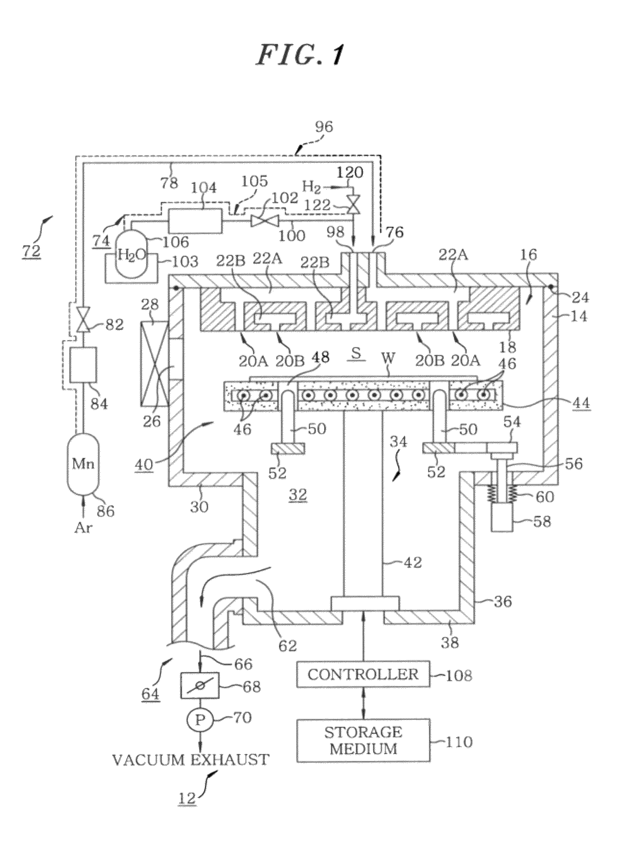
[0048]FIG. 1 illustrates a configuration of a film forming apparatus in accordance with a first embodiment of the present invention. The film forming apparatus in accordance with the first embodiment is used to form a Mn-containing film including a transition metal. In the following embodiments to be described below, water vapor (H2O) is used as an oxygen-containing gas. As shown in FIG. 1, a film forming apparatus 12 in accordance with the embodiment of the present invention includes a processing chamber 14 made of aluminum and having an approximately cylindrical inner space. A shower head 16 serving as a gas introduction unit is provided at a ceiling of the processing chamber 14 to introduce a desired processing gas, e.g., a film forming gas. A gas injection surface 18 that is a bottom surface of the shower head 16 has a plurality of gas injection holes 20A and 20B through which the processing gas is injected to a processing space S.

[0049]Two separate gas diffusion spaces 22A and ...

second embodiment

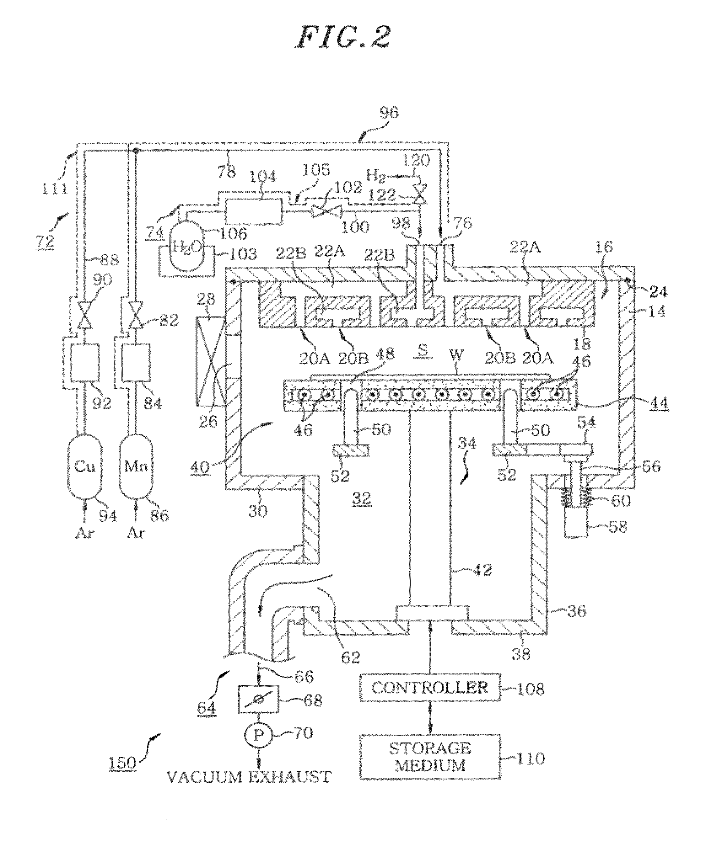
[0064]Hereinafter, a film forming apparatus in accordance with a second embodiment of the present invention will be described in detail. FIG. 2 illustrates a configuration of the film forming apparatus in accordance with the second embodiment of the present invention. The film forming apparatus 150 is used to form a CuMn-containing alloy film including a transition metal. However, if a Cu-containing source gas is not used, the above apparatus may also form a Mn-containing film. In FIG. 2, the constitutional components substantially the same as those of FIG. 1 are represented by the same reference numerals and a description thereof will be omitted.

[0065]The film forming apparatus 150 of the second embodiment further includes a branch line 88 diverged from the source gas line 78 through which a transition metal-containing source gas flows. The branch line 88 is connected to a second material supply source 94 containing a second material through a switching valve 90 and a flow rate con...

first and second embodiments

for Methods of the Invention

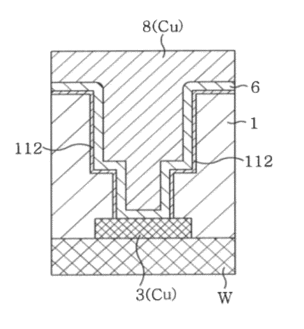
[0071]Hereinafter, a film forming method in accordance with the embodiments of the present invention will be described in detail with reference to FIGS. 3A to 6C. FIGS. 3A to 3D illustrate thin film deposition in a recess of a semiconductor wafer during individual processes. FIGS. 4A and 4B are flowcharts showing some of the processes of the film forming method in accordance with the first and second embodiments of the present invention. FIG. 4A depicts a film forming method for forming a Mn-containing film in accordance with the first embodiment of the present invention, and FIG. 4B depicts a film forming method for forming a CuMn-containing film in accordance with the second embodiment of the present invention. FIGS. 5A and 5B are timing graphs illustrating gas supplying states by CVD and ALD, respectively, in formation of a seeding film of a Mn-containing film. FIGS. 6A to 6C are timing graphs illustrating gas supply states by CVD and ALD, respectively...


PUM

PropertyMeasurementUnit
inner diameteraaaaaaaaaa
aspect ratioaaaaaaaaaa

Abstract

On a surface of an object to be treated, a Mn-containing thin film or CuMn-containing alloy thin film is formed by heat treatment (CVD or ALD) by using a Mn-containing source gas (or Mn-containing source gas and a Cu-containing gas) and an oxygen-containing gas (for instance, water vapor) as a processing gas. The Mn-containing thin film or the CuMn-containing alloy thin film can be formed with high step coverage in a fine recess formed on the surface of the object to be treated.

Description

[0001]This application is a Continuation Application of PCT International Application No. PCT / JP2008 / 060159 filed on Jun. 2, 2008, which designated the United States.FIELD OF THE INVENTION[0002]The present invention relates to a film forming method and a film forming apparatus for forming a manganese (Mn) containing film or a copper-manganese (CuMn) containing alloy film, as a seeding film, on a surface of an object to be treated such as a semiconductor wafer.BACKGROUND OF THE INVENTION[0003]In general, in order to manufacture semiconductor devices, a semiconductor wafer is repeatedly subjected to various treatments such as a film forming process and a pattern etching process to form desired devices. With increased requirements for highly integrated and miniaturized semiconductor devices, a line width and / or a hole diameter of the device is currently being reduced. Along with reduction in various dimensions of the device, a lower electric resistance is required. In order to meet the...

Claims


Application Information

Patent Timeline
Patent Type & Authority Patents(United States)
IPC IPC(8): H01L21/4763
CPCC23C16/045C23C16/18C23C16/40C23C16/408C23C16/45525C23C16/45531C23C16/56H01L21/28562H01L21/76831H01L21/76843H01L21/76844H01L21/76855H01L21/76864H01L21/76867H01L21/76873H01L23/53238H01L2924/0002H01L2924/09701H01L2924/00H01L21/205H01L21/285
Inventor MATSUMOTO, KENJIITOH, HITOSHINEISHI, KOJIKOIKE, JUNICHI
Owner TOKYO ELECTRON LTD
Why Eureka
Try Eureka