Method and system for recycling flue gas

a flue gas and heat recovery technology, applied in the direction of combustible gas production, combustible gas purification/modification, sustainable manufacturing/processing, etc., can solve the problem of difficult to find useful applications for large quantities of heat, and achieve the effect of reducing the amount of feedstock required and increasing the reaction ra

Inactive Publication Date: 2012-08-21
KUTSIN LEONID
View PDF15 Cites 20 Cited by
  • Summary
  • Abstract
  • Description
  • Claims
  • Application Information

AI Technical Summary

Benefits of technology

[0035]A method of utilizing the system may be achieved by performing the following steps: starting a thermochemical reaction within a gasification reactor by loading an appropriate volume of coal or other biomass fuel; introducing hot flue or exhaust gases from a heat or power generator being oxygen poor and CO2 ri

Problems solved by technology

When petroleum and natural gas were very expensive, it is a necessity to use biomass, coal and other carbonaceous source as fuel.
It is often

Method used


Image

  • Method and system for recycling flue gas
  • Method and system for recycling flue gas
  • Method and system for recycling flue gas

Examples


Embodiment Construction

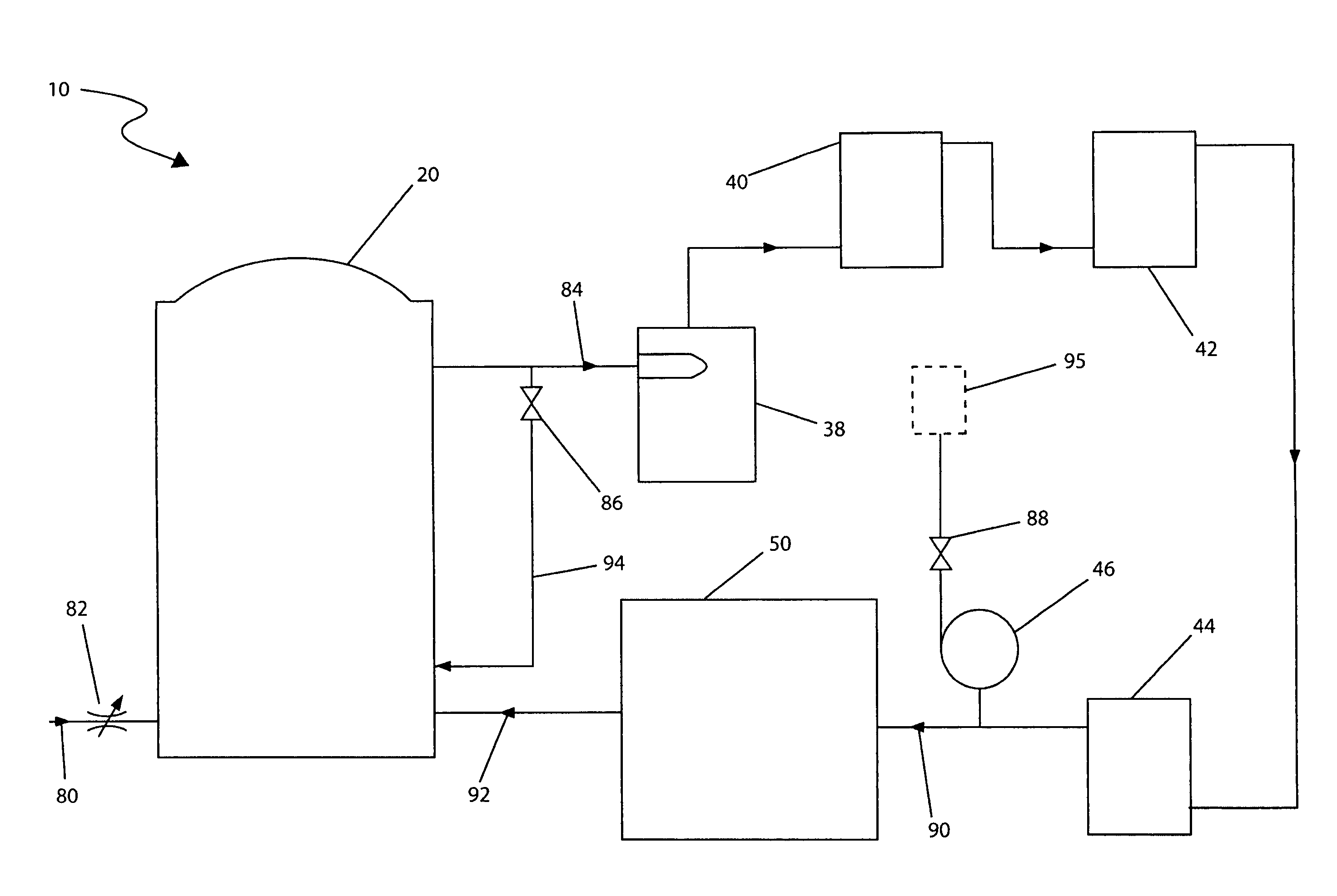
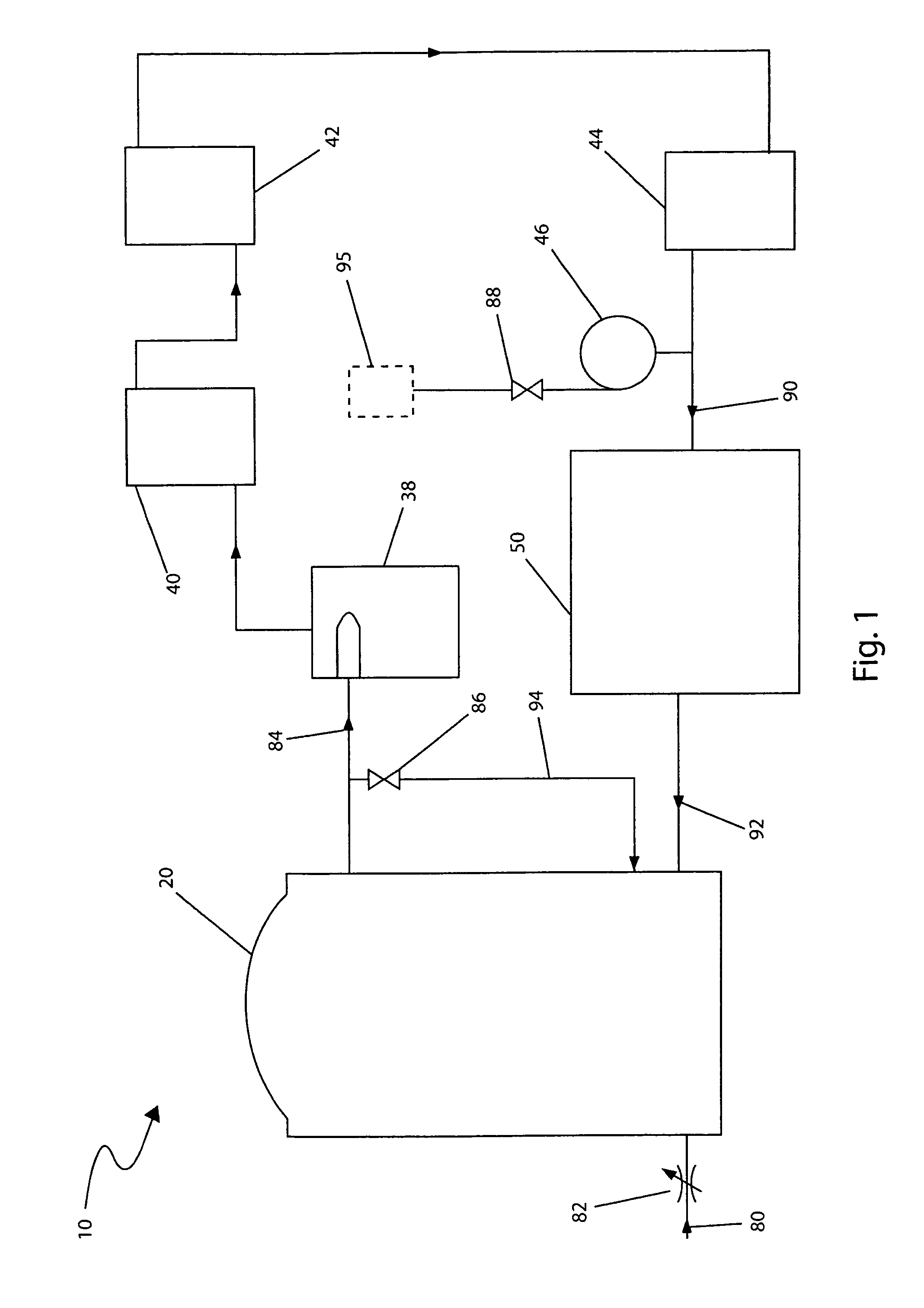
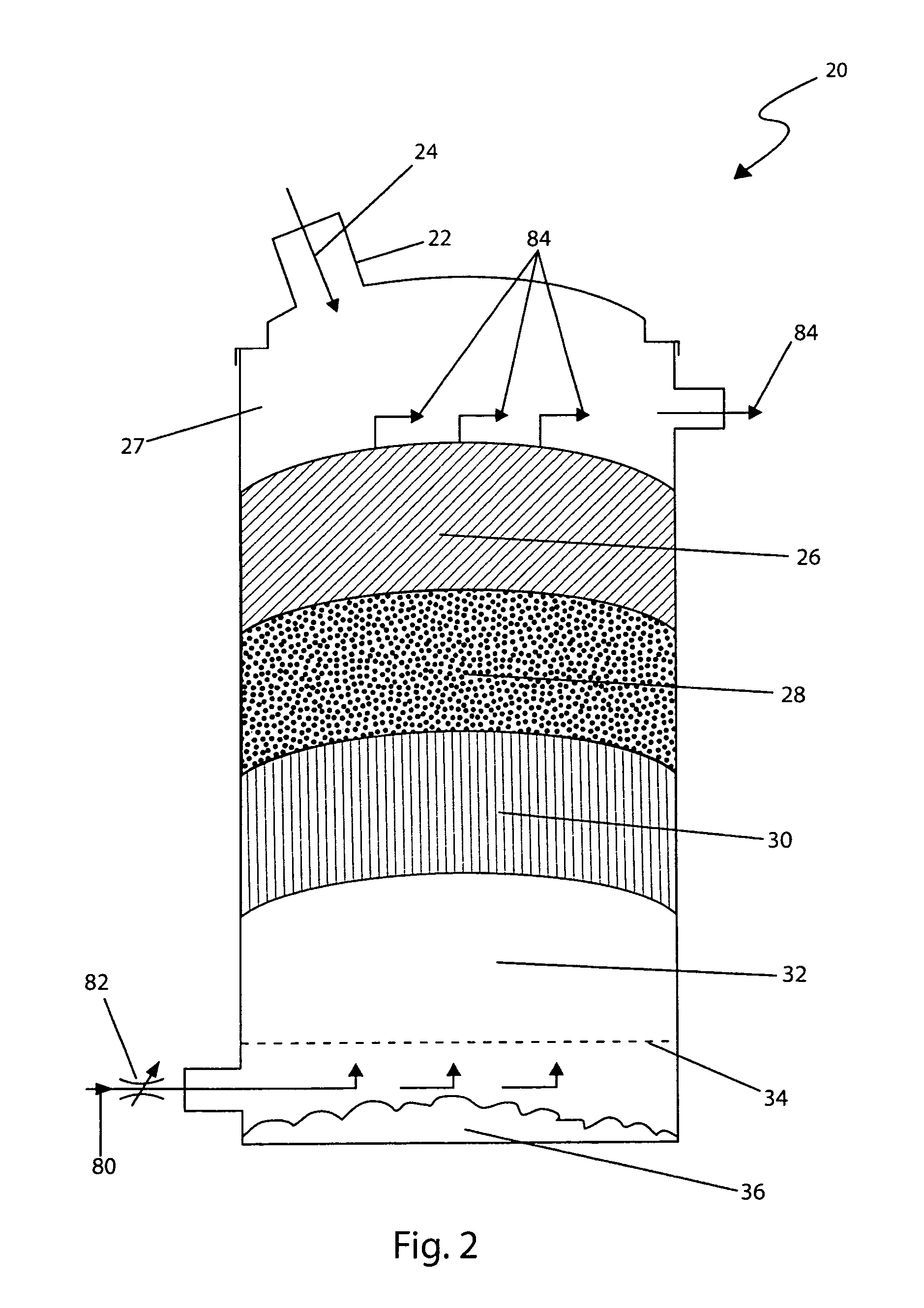
[0041]The best mode for carrying out the invention is presented in terms of its preferred embodiment, herein depicted within FIGS. 1 and 2 and alternately in FIG. 3. However, the invention is not limited to the described embodiment and a person skilled in the art will appreciate that many other embodiments of the invention are possible without deviating from the basic concept of the invention, and that any such work around will also fall under scope of this invention. It is envisioned that other styles and configurations of the present invention can be easily incorporated into the teachings of the present invention, and only one particular configuration shall be shown and described for purposes of clarity and disclosure and not by way of limitation of scope.

[0042]The terms “a” and “an” herein do not denote a limitation of quantity, but rather denote the presence of at least one of the referenced items.

[0043]The present invention describes a system to utilize carbon dioxide (CO2) and...


PUM


Abstract

An improved process to reduce emissions converts carbon dioxide from the flue gas exhaust from heat or power generators, into synthetic gas which is in-turn reintroduced back into the generator as fuel, is herein disclosed. Hot flue and exhaust gases from power generators, which contain carbon dioxide, would be blown into a gasification reactor, which contains coal, wood chips or other carbon based fuels substances. The process utilizes gasification technology to create a thermochemical reaction between the carbon dioxide and the fuel via a high temperature and no-oxygen atmosphere to produce synthetic gas. The synthetic gas includes carbon monoxide and hydrogen which is then fed back into a heat or power generator as fuel. The process may include two (2) or more reactors, thereby allowing one (1) reactor to be loaded or unloaded while synthetic gas continues to be produced by the other reactor. The synthetic gas may also be further converted into vehicle fuels and other useful chemicals.

Description

RELATED APPLICATIONS[0001]The present invention was first described in U.S. Provisional Patent Application No. 61 / 005,538 filed on Dec. 6, 2007, the entire disclosures of which are incorporated herein by reference.FIELD OF THE INVENTION[0002]The present invention relates to an improved process for utilization of carbon dioxide and heat of flue and exhaust gas, particularly from heat and power generators by a thermochemical conversion of carbon dioxide into ecologically manageable synthetic gas without pollution during said process.BACKGROUND OF THE INVENTION[0003]The “going green” movement is one that has picked up tremendous momentum in the United States. From energy and water conservation, to recycling, to buying organic foods and even clothing, people are more earth-conscious than ever. One (1) of the most popular means of going green involves reducing fossil fuel consumption. As available supplies dwindle, it is apparent that there is a need for a system to converting carbon dio...

Claims


Application Information

Patent Timeline
IPC IPC(8): C01B3/36C01B6/24C01B3/02C10J3/00B01J7/00
CPCC10J3/463C10K1/024C10J2300/1606C10J2300/1659C10J2300/1815C01B2203/0222C01B2203/062C01B2203/86Y02P20/129Y02P30/00
Inventor KUTSIN, LEONID
Owner KUTSIN LEONID
Why Eureka
Try Eureka