Display device
a technology of a display device and a display device, which is applied in the field of display devices, can solve the problems of insufficient structure of the above-described structure in order to improve the characteristics of the transistor, and achieve the effects of reducing the number of hydrogen atoms, reducing the density of the carrier, and reducing the off-state current of the transistor
- Summary
- Abstract
- Description
- Claims
- Application Information
AI Technical Summary
Benefits of technology
Problems solved by technology
Method used
Image
Examples
embodiment 1
[Embodiment 1]
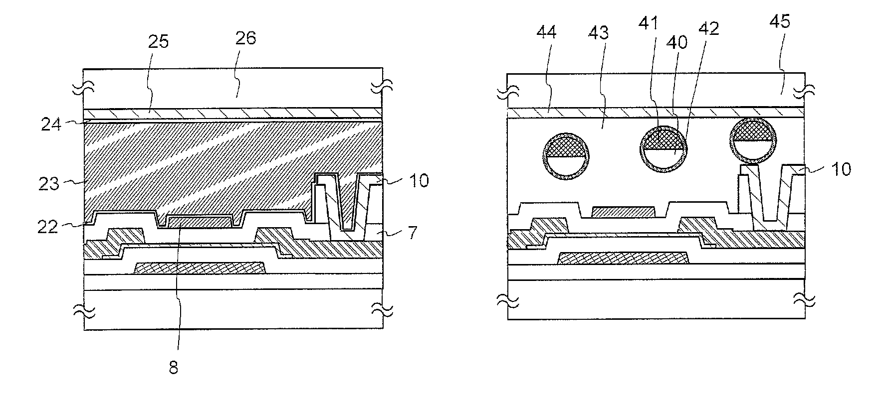
[0048]This embodiment discloses a display device including a first gate electrode; a first gate insulating film formed over the first gate electrode; an oxide semiconductor film formed over the first gate insulating film; and a source electrode and a drain electrode formed over the oxide semiconductor film. The source electrode and the drain electrode are electrically connected to the oxide semiconductor film. A second gate insulating film formed over the source electrode, the drain electrode, and the oxide semiconductor film; and a second gate electrode formed over the second gate insulating film are provided. The second gate electrode is electrically connected to the first gate electrode. An organic resin film having flatness formed over the second gate insulating film and a pixel electrode formed over the organic resin film having flatness are provided. The pixel electrode is electrically connected to either the source electrode or the drain electrode, and a display...
example 1
[0176]In this example, a method for calculating the carrier density of an oxide semiconductor film is described with reference to FIGS. 17, 18A and 18B.
[0177]First, the structure of a sample used in a C-V (Capacitance-Voltage) measurement is described with reference to FIG. 17.
[0178]A titanium film 503 with a thickness of 300 nm was formed by a sputtering method over a glass substrate 501 and a titanium nitride film 505 with a thickness of 100 nm was formed by a sputtering method thereover.
[0179]As an oxide semiconductor film 507 in which the number of hydrogen atoms were reduced, an In—Ga—Zn—O film with a thickness of 2000 nm was formed by a sputtering method over the titanium nitride film 505. The deposition condition at this time was as follows: as the sputtering gas, Ar at a flow rate of 30 sccm and oxygen at a flow rate of 15 seem were used, the distance between the target and the substrate was 60 mm, the direct current (DC) power was 0.5 kW, and the deposition atmosphere tempe...
example 2
[0185]In this example, with regard to an oxide semiconductor film in which the number of hydrogen atoms are reduced by heat treatment, the results of TEM analysis are described.
[0186]First, a method for manufacturing a sample is described.
[0187]An oxide semiconductor film was formed by a sputtering method over a substrate 601.
[0188]Here, as the substrate 601, EAGLE XG substrate (manufactured by Corning Incorporated) was used. As the oxide semiconductor film, an In—Ga—Zn—O film 603 was deposited with the use of an oxide semiconductor target of In2O3:Ga2O3:ZnO=1:1:1. The sample is referred to as sample B which is a comparative example. The number of hydrogen atoms is not reduced in the sample B.
[0189]Next, heat treatment was performed on the In—Ga—Zn—O film 603 at 650° C. for one hour in a nitrogen gas atmosphere with the use of an electric furnace, whereby the number of hydrogen atoms was reduced. The In—Ga—Zn—O film on which heat treatment was performed is referred to as an oxide se...
PUM
 Abstract
Description
Claims
Application Information
 - R&D
- Intellectual Property
- Life Sciences
- Materials
- Tech Scout
- Unparalleled Data Quality
- Higher Quality Content
- 60% Fewer Hallucinations
Browse by: Latest US Patents, China's latest patents, Technical Efficacy Thesaurus, Application Domain, Technology Topic, Popular Technical Reports.
© 2025 PatSnap. All rights reserved.Legal|Privacy policy|Modern Slavery Act Transparency Statement|Sitemap|About US| Contact US: help@patsnap.com


