
Apartment-shaped anaerobic digester for producing biogas

an anaerobic digester and apartment-shaped technology, which is applied in the direction of gas production bioreactors, feed/discharge of settling tanks, sedimentation separation, etc., can solve the problems of inability to optimally control the acid production and methanogenesis steps, inability to maintain stability, and disadvantage in terms of costs, so as to reduce the cost of production and production, inhibit growth and development, and improve the efficiency of biogas production

Inactive Publication Date: 2012-10-30
LEE SANG BUM
View PDF11 Cites 0 Cited by
  • Summary
  • Abstract
  • Description
  • Claims
  • Application Information

AI Technical Summary

Benefits of technology

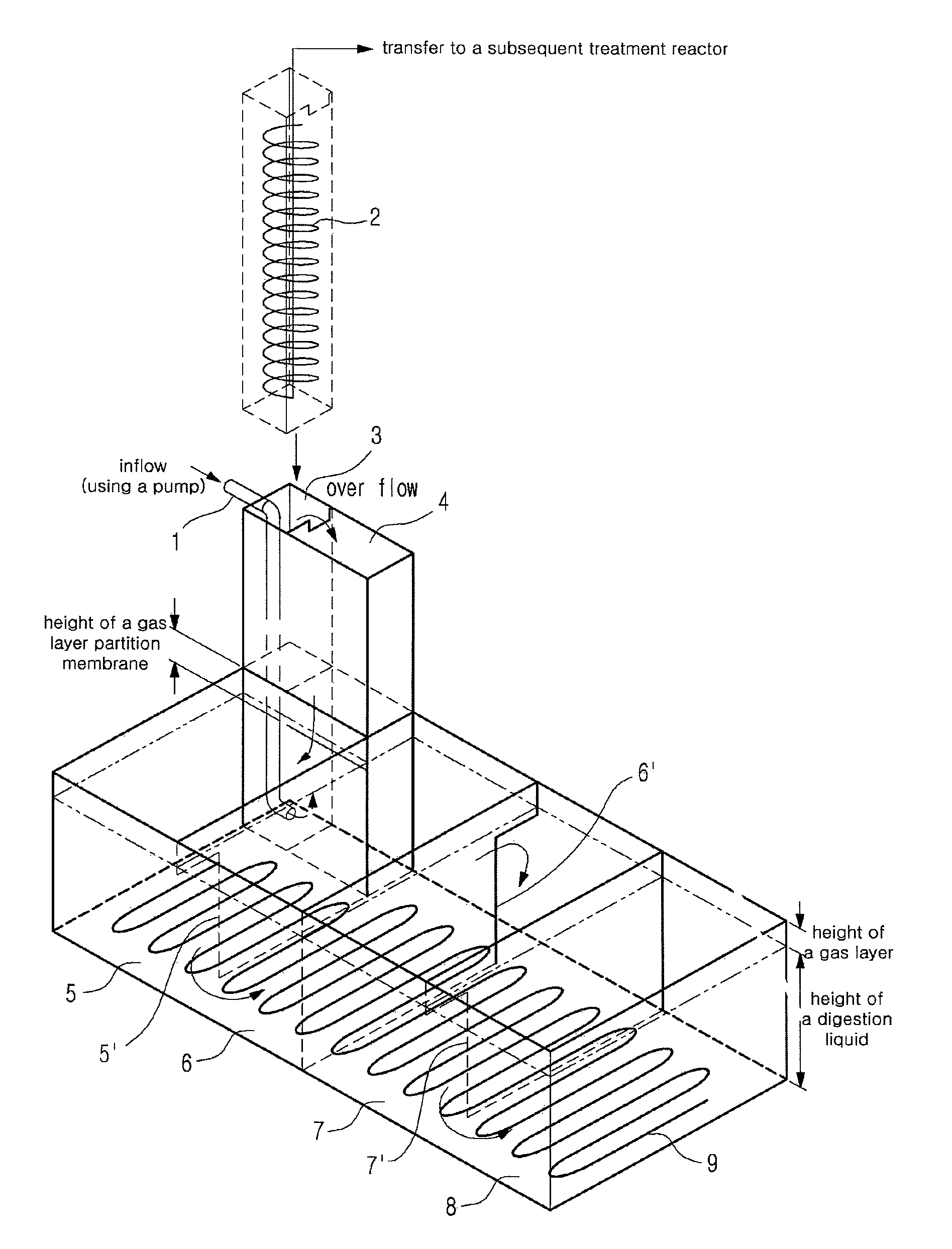
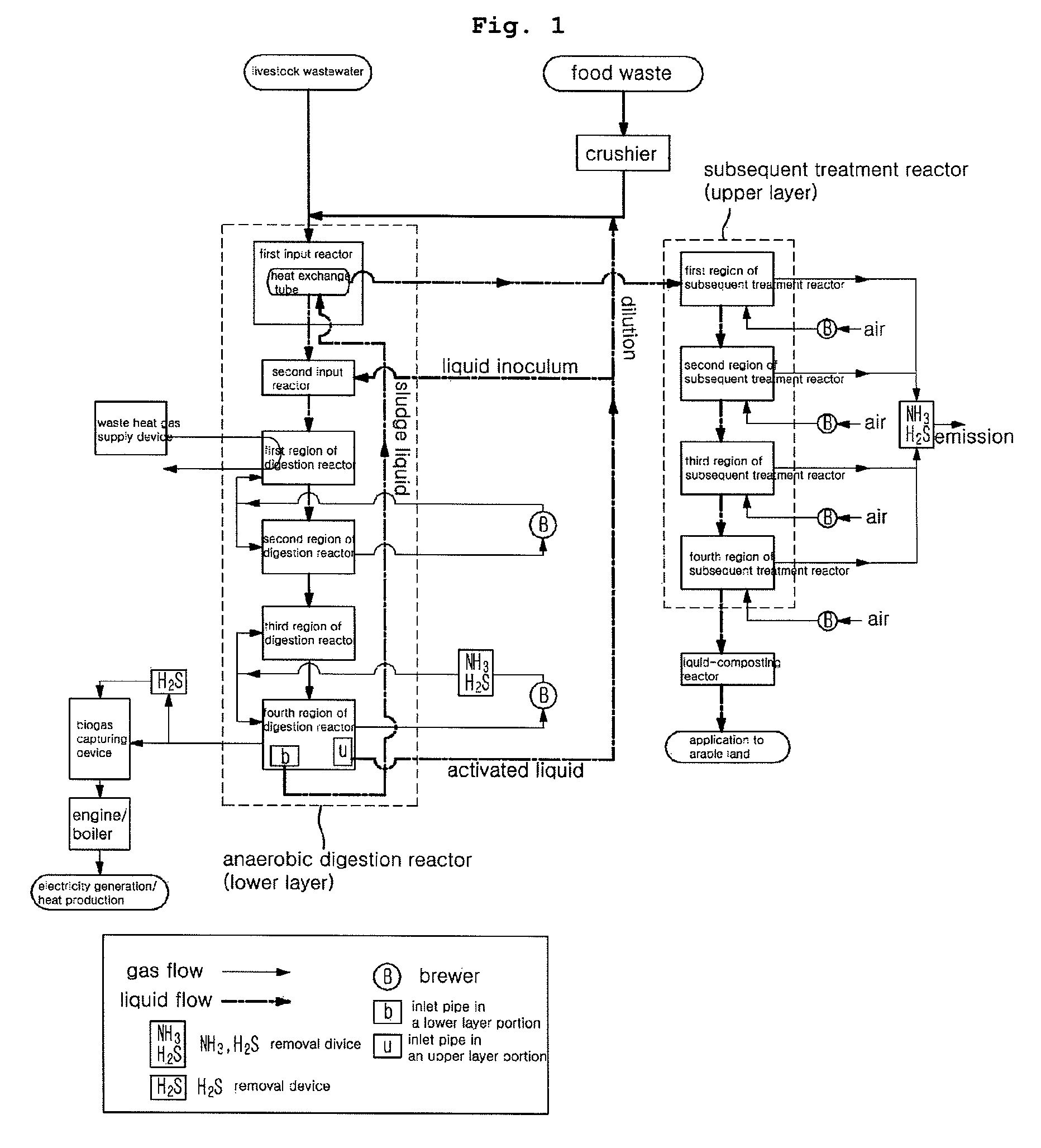
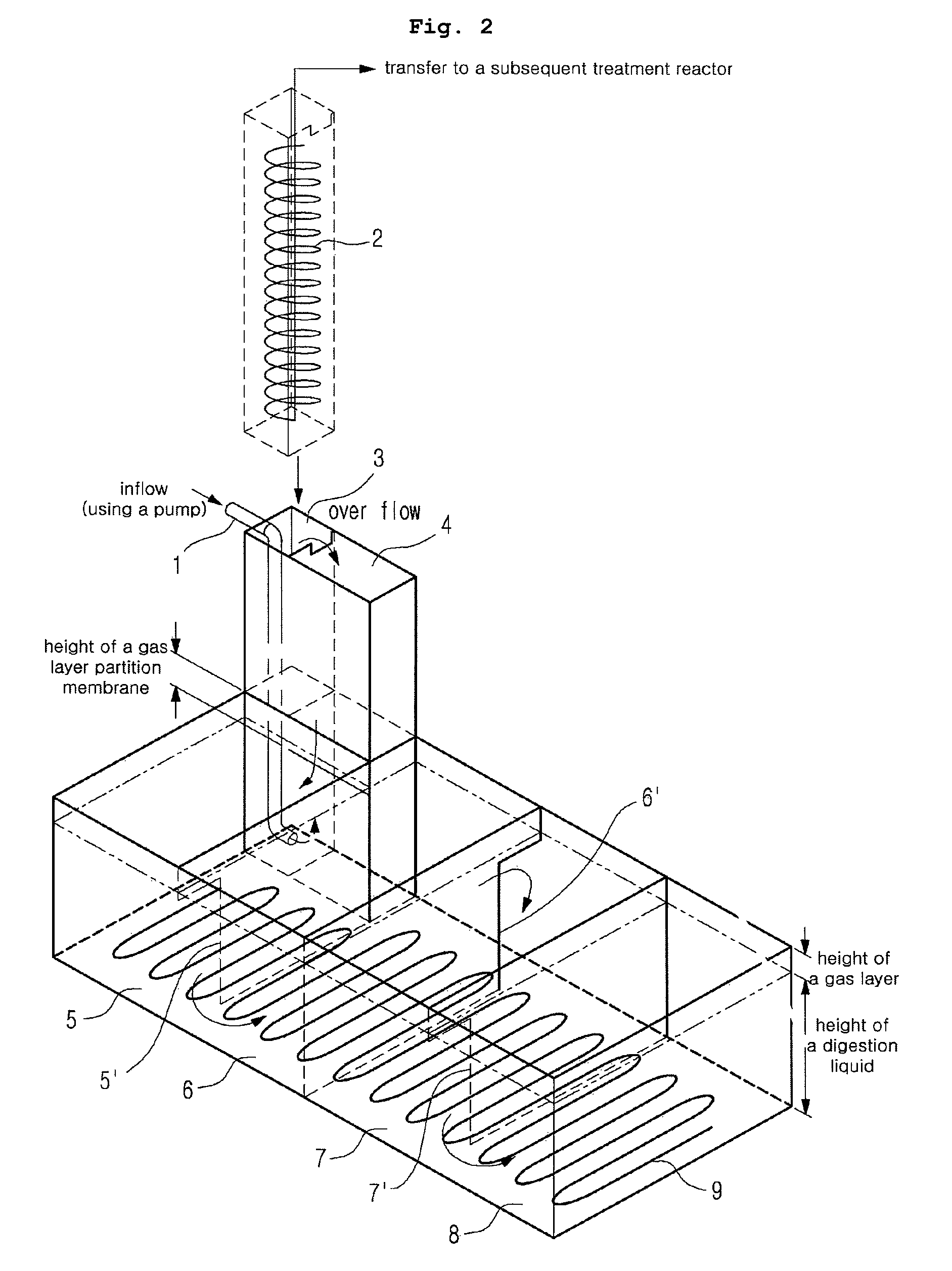
"The present invention provides an anaerobic digester that is simple and efficient in producing biogas. It includes a reactor with multiple regions for optimal anaerobic digestion, a diffusing gas supply tube and diffuser, an inlet pipe for sludge liquid and activated liquid, a biogas capturing device, a heat exchange tube, a treatment reactor for removing odor components, and a liquid-composting reactor. The anaerobic digester does not require a separate gas storage unit and has low-cost ammonia and hydrogen sulfide removal device that prevents the growth and development of methanogen and removes 99% or more of ammonia and hydrogen sulfide. It also induces floatation and homogenization of deposits in the inflow and produces a biogas with high methane content."

Problems solved by technology

Because acid production and methanogenesis occur simultaneously in a reactor in the traditional first step reaction process (one-phase method), there are limitations in that it is impossible to optimally control the acid production and methanogenesis steps, and stability is not maintained due to its sensitivity to changes in externally-introduced waste.
However, these two-phase methods are disadvantageous in terms of costs because reactors must be separately provided, thereby requiring a system for transfer from a first reactor to a second reactor, and are complicated in that reaction conditions in each reactor must be separately controlled.

Method used


Image

  • Apartment-shaped anaerobic digester for producing biogas
  • Apartment-shaped anaerobic digester for producing biogas
  • Apartment-shaped anaerobic digester for producing biogas

Examples


Embodiment Construction

[0026]Features and advantages of the present invention will be more clearly understood by the following detailed description of the present preferred embodiments by reference to the accompanying drawings. It is first noted that terms or words used herein should be construed as meanings or concepts corresponding to the technical spirit of the present invention, based on the assumption that the inventor has appropriately define the concepts of the terms to best describe the present invention. Also, it should be understood that detailed descriptions of well-known functions and structures related to the present invention are not provided so as not to unnecessarily obscure the essence of the present invention.

[0027]The present invention provides an apartment-shaped anaerobic digester which may increase the production efficiency of biogas by providing optimal anaerobic digestion conditions under which acid production and methanogenesis steps may be simultaneously performed in one anaerobi...


PUM

PropertyMeasurementUnit
temperatureaaaaaaaaaa

Abstract

Disclosed herein is an anaerobic digester configured to include input reactors into which livestock wastewater or food waste (hereinafter, ‘inflow’) is introduced; regions of an anaerobic digestion reactor designed for the inflow passing through an input reactor to perform methane fermentation to produce and transfer biogas simultaneously into the next region; an inlet pipe into which sludge liquid is drawn; an inlet pipe into which activated liquid is drawn; a biogas capturing device; a first heat exchange tube to allow the sludge liquid to perform heat exchange with a new inflow; regions of a subsequent treatment reactor to allow the sludge liquid whose heat exchange is completed to be introduced and to treat gas odor components generated from the sludge liquid; and a liquid-composting reactor in which the emitted sludge whose odor components have been removed is stored.

Description

CROSS-REFERENCES TO RELATED APPLICATION[0001]This patent application claims the benefit of priority from Korean Patent Application No. 10-2009-0012435, filed on Feb. 16, 2009, the contents of which are incorporated herein by reference.BACKGROUND OF THE INVENTION[0002]1. Field of the Invention[0003]The present disclosure relates to an apartment-shaped anaerobic digester for producing biogas.[0004]2. Description of the Related Art[0005]Anaerobic digestion, also known as “methane fermentation”, is a biological treatment method for stabilizing organic waste such as food waste, livestock waste, sewage sludge, manure, etc., and a treatment method for hydrolyzing high-molecular organic materials in the presence of facultative and obligate anaerobes under anaerobic conditions, producing volatile fatty acids such as acetic, propionic, butyric acids, etc., and finally gasifying them into methane, hydrogen, carbon dioxide, ammonia, and hydrogen sulfide.[0006]These anaerobic digestions have not...

Claims


Application Information

Patent Timeline
Patent Type & Authority Patents(United States)
IPC IPC(8): C02F3/28
CPCC02F3/282C12M21/04C12M23/36C12M27/20C12M29/06C12M41/18C12P5/023C02F3/286Y02E50/343C02F2103/20C02F2103/32C02F2209/02C02F2209/04C02F2209/06C02F2303/02Y02E50/30Y02W10/10Y02W30/40
Inventor LEE, SANG BUMLEE, KE HO
Owner LEE SANG BUM
Learn More