
Microchip and wedge ion funnels and planar ion beam analyzers using same

a funnel and microchip technology, applied in the field of system and method of focusing of ions, can solve the problems of major ion loss, ion transfer into the ms, and most real samples are sufficiently challenging, and achieve the effect of higher breakdown threshold

Active Publication Date: 2012-10-30
BATTELLE MEMORIAL INST
View PDF20 Cites 42 Cited by
  • Summary
  • Abstract
  • Description
  • Claims
  • Application Information

AI Technical Summary

Benefits of technology

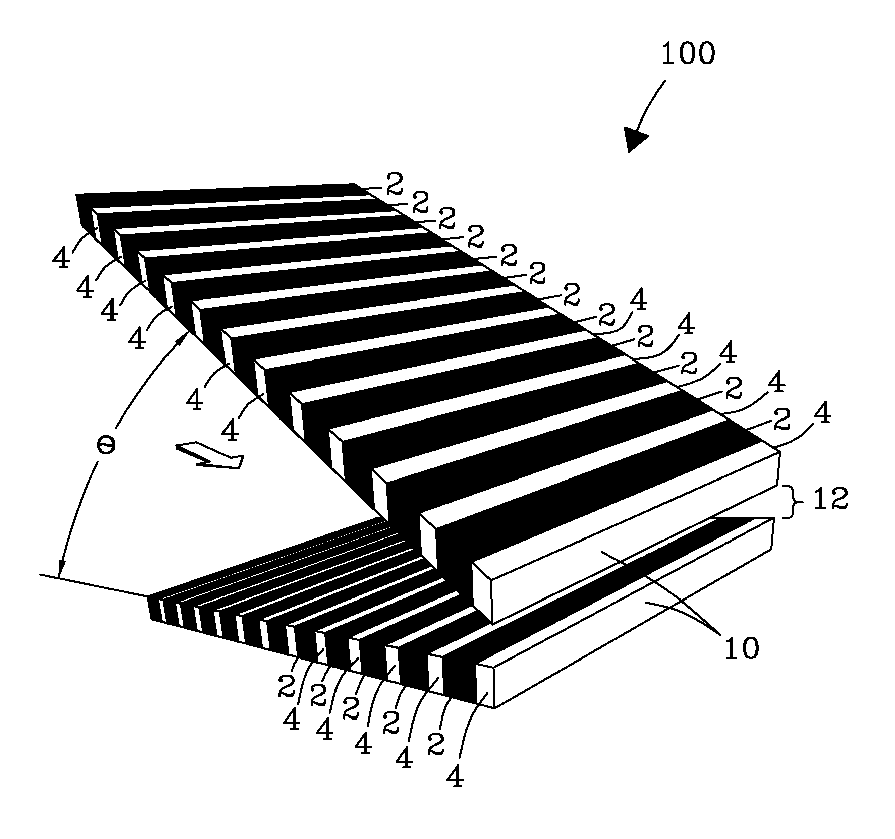
The invention is about creating devices that use RF electric fields to focus ions in gases at high pressures. These devices are built using the MEMS platform and technology, and they have smaller features using the "wedge" geometry. The devices operate at high pressures, ranging from 50 Torr to about 1 atm. The invention also includes planar ion beam analyzers that use the same technology. The devices use microscopic gaps with electrodes to create an ion-guiding tunnel for ions to pass through. The invention also includes a method for compressing ion beams using a wedge funnel and a longitudinal electric field. The invention can be used in various applications such as mass spectrometry, ion mobility spectrometry, and photoelectron spectrometry.

Problems solved by technology

Most real samples are sufficiently challenging to necessitate one or more separation steps prior to MS.
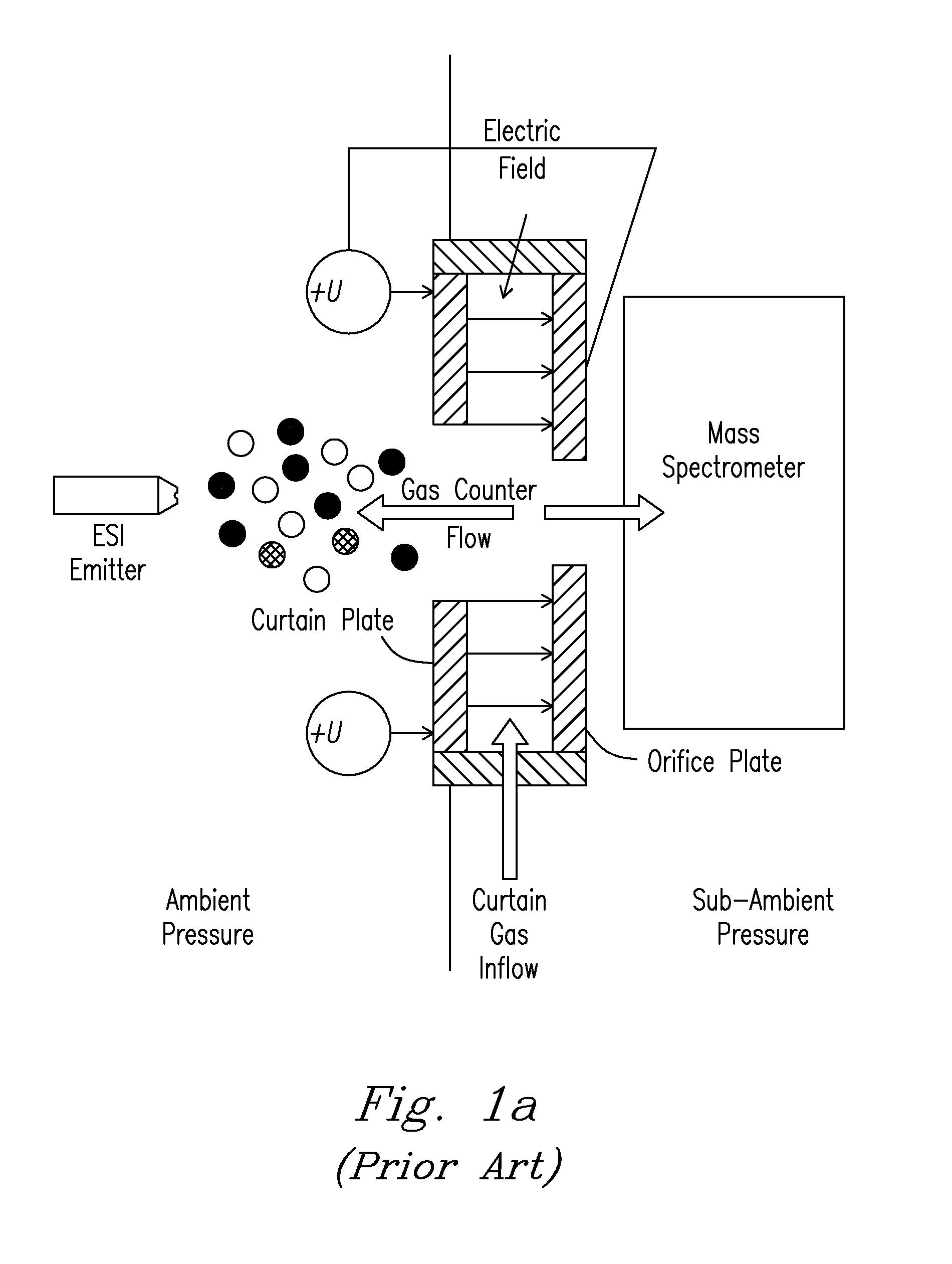
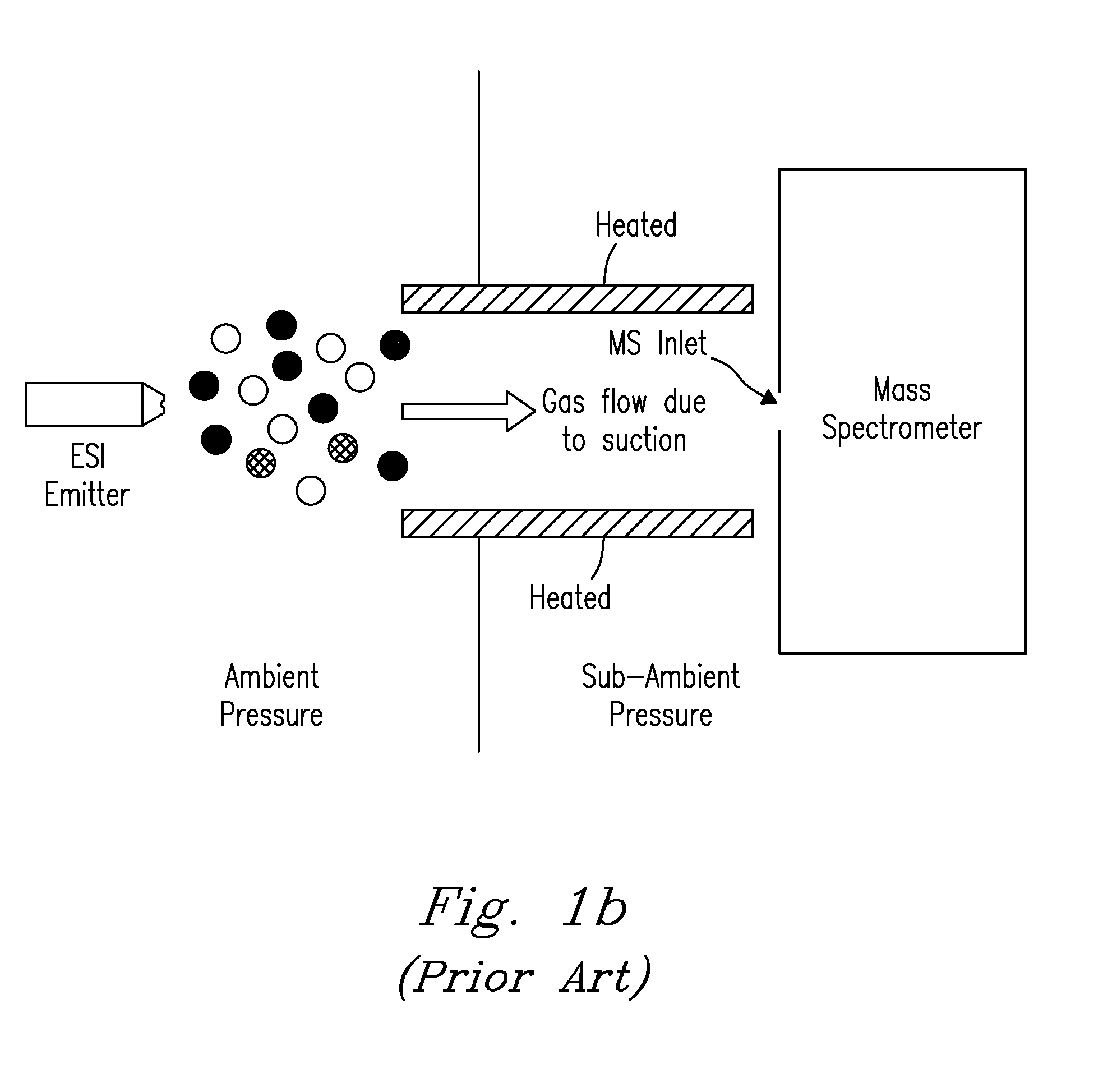
Use of such atmospheric pressure ionization (API) sources inevitably creates the problem of effective ion transfer into the MS vacuum through a necessarily narrow orifice that is typically much smaller than the produced ion swarm.
The same issue arises when coupling IMS or FAIMS stages among themselves or to MS, where ion beams or packets that spread (because of diffusion and Coulomb repulsion) during separation must be introduced into an MS or another IMS stage via a narrow aperture.
In either case, the conductance limit between the atmosphere and MS vacuum is much narrower than the incoming ion plume, leading to major ion losses even with a single ESI emitter.
Thus the gas coming from atmosphere supersonically expands, greatly broadening the ion beams beyond the aperture of the skimmer leading to the next MS chamber, which causes further losses.
Thus ˜1% and often much less of ions produced by ESI are transmitted to the high-vacuum MS regions, limiting the MS sensitivity and dynamic range.
In conjunction with losses at the tube front and low DTIMS duty cycle, that has reduced sensitivity so severely as to preclude commercialization of DTIMS / MS systems and their use in most practical analyses.
This focusing also constrains the FANS resolving power, obstructing many applications.
Extracting such broadened beams through standard inlets to an MS (or reduced-pressure IMS) stage is associated with huge ion losses that limit the utility of high-resolution FAILS (FIG. 1e).
Slit-aperture MS inlets that better match the rectangular cross-section of ion beams exiting planar FAIMS devices provide some improvement, but large losses remain.
Thus API / MS inlets were restricted to c˜0.3 mm2, resulting in large ion losses at the inlet faces and materially constraining the capabilities and utility of IMS / MS platforms.
However, losses are still large and further increase of the operating pressure and gas intake is desired.
However, w and A could not be raised further within the existing paradigm of funnel assembly from individually machined macroscopic electrodes.
While this virtually eliminates ion losses, the lower efficiency of ESI at 30 Torr offsets that, and the final ion yield is close to that using atmospheric-pressure ESI with multicapillary inlet / tandem ion funnel interface.
The resulting space-charge expansions limit the resolving power of MS [in particular, orthogonal time-of-flight (o-ToF) MS] or IMS systems and their sensitivity, as ions exceeding the analyzer charge capacity are eliminated.
Large ion flux gains provided by funnel interlaces known in the art already cause notable peak broadening in DTIMS, which would worsen as funnels at higher pressures deliver even greater ion currents.

Method used


Image

  • Microchip and wedge ion funnels and planar ion beam analyzers using same
  • Microchip and wedge ion funnels and planar ion beam analyzers using same
  • Microchip and wedge ion funnels and planar ion beam analyzers using same

Examples


Embodiment Construction

[0030]The invention provides effective RF ion focusing across the range of ion mass-to-charge ratios most relevant to proteomics and metabolomics (˜300-3,000) at P>0.1 atm. In particular, the pressure may range from 0.3 to 1 atm and even exceed 1 atm, Even P=0.3 atm allows ESI (in the form of SPIN sources) and IMS / MS to perform virtually as well as at ambient pressure.

[0031]As detailed herein, extensive characterization of 2nd-generation ion funnels has proven the theory that the maximum operating pressure scales with w and A. The underlying physics has no pressure limit and must equally apply up to P=1 atm and beyond. Then effective ion focusing at P=1 atm (or ˜25 times the present value of P=30 Torr) would require w ˜50 MHz and, in the current funnel geometry, U=5 kV or A=100 kV / cm, Reaching those values would necessitate augmenting the electrical power output by 254=390,625 times, an impossible proposition from either the power consumption or heat release viewpoints. Also, the br...


PUM


Abstract

Electrodynamic ion funnels confine, guide, or focus ions in gases using the Dehmelt potential of oscillatory electric field. New funnel designs operating at or close to atmospheric gas pressure are described. Effective ion focusing at such pressures is enabled by fields of extreme amplitude and frequency, allowed in microscopic gaps that have much higher electrical breakdown thresholds in any gas than the macroscopic gaps of present funnels. The new microscopic-gap funnels are useful for interfacing atmospheric-pressure ionization sources to mass spectrometry (MS) and ion mobility separation (IMS) stages including differential IMS or FAIMS, as well as IMS and MS stages in various configurations. In particular, “wedge” funnels comprising two planar surfaces positioned at an angle and wedge funnel traps derived therefrom can compress ion beams in one dimension, producing narrow belt-shaped beams and laterally elongated cuboid packets. This beam profile reduces the ion density and thus space-charge effects, mitigating the adverse impact thereof on the resolving power, measurement accuracy, and dynamic range of MS and IMS analyzers, while a greater overlap with coplanar light or particle beams can benefit spectroscopic methods.

Description

FEDERALLY-SPONSORED RESEARCH AND DEVELOPMENT[0001]This invention was made with Government support under Contract DE-AC06-76RLO1830 awarded by the U.S. Department of Energy. The Government has certain rights in the invention.FIELD OF THE INVENTION[0002]The invention relates to systems and methods for guidance and focusing of ions, particularly in the context of mass spectrometry (MS) and ion mobility spectrometry (IMS). Specifically, the invention discloses an electrodynamic ion funnel of new design and construction technology, and novel MS and IMS operational modes that it enables.BACKGROUND OF THE INVENTION[0003]Modern biomedical and environmental research and applications depend on detailed and comprehensive characterization of complex samples. The demands of specificity, sensitivity, and speed have made mass spectrometry (MS) the prevailing platform for such analyses. Most real samples are sufficiently challenging to necessitate one or more separation steps prior to MS. These sep...

Claims


Application Information

Patent Timeline
Patent Type & Authority Patents(United States)
IPC IPC(8): H01J49/42H01J49/04
CPCH01J49/0018H01J49/066
Inventor SHVARTSBURG, ALEXANDRE A.ANDERSON, GORDON A.SMITH, RICHARD D.
Owner BATTELLE MEMORIAL INST
Learn More