Combination laser and charged particle beam system

a laser beam and charged particle technology, applied in the field of laser beam system combination, can solve the problems of high-precision milling or sample removal often requiring tradeoffs, ion beams tend to damage sample surfaces, and limited processing rate of liquid metal ion sources

Active Publication Date: 2012-11-20
FEI CO
View PDF31 Cites 20 Cited by
  • Summary
  • Abstract
  • Description
  • Claims
  • Application Information

AI Technical Summary

Benefits of technology

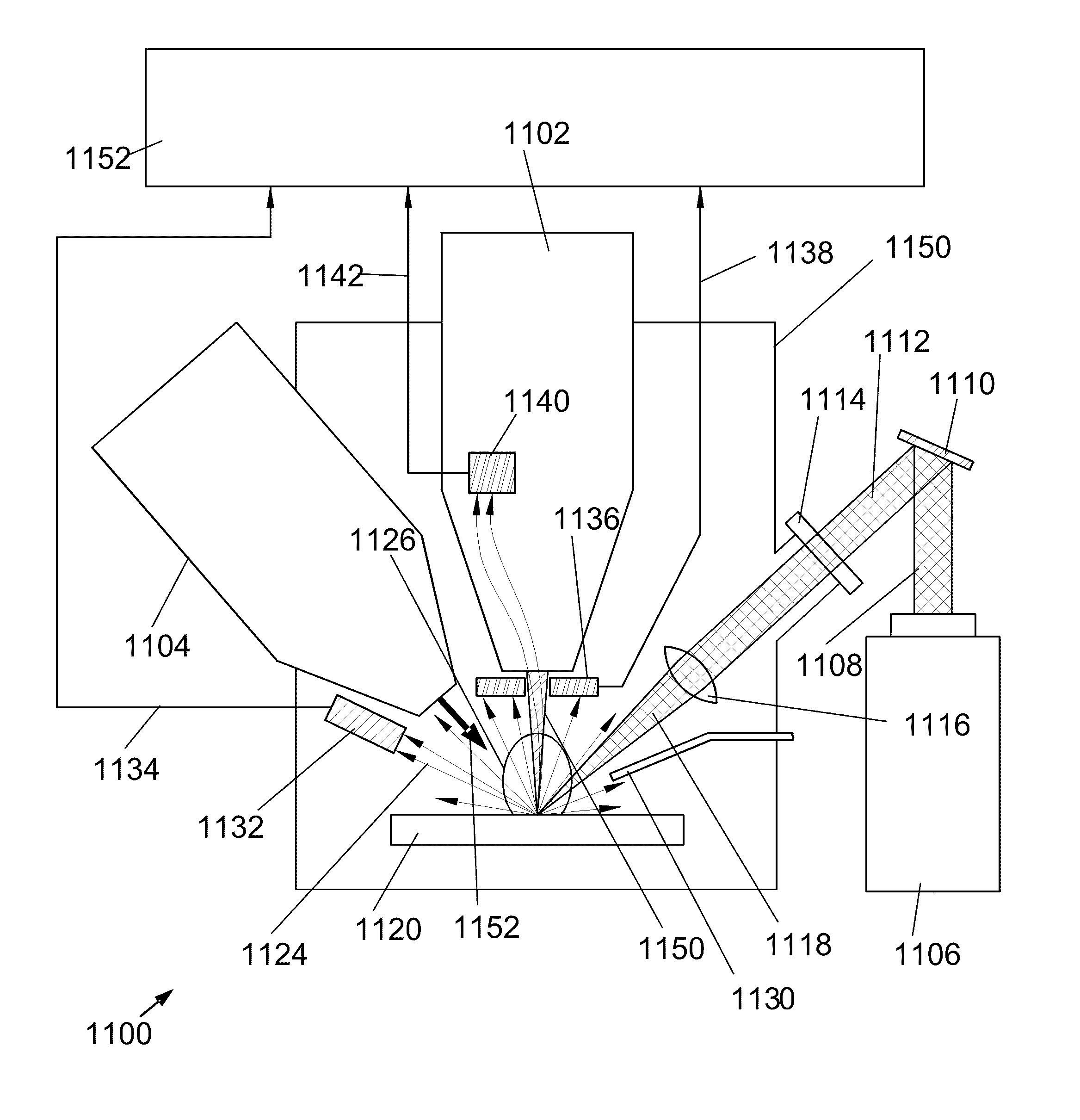
[0015]Another object of the invention is to provide a method for preventing imaging detectors (“type-1” detectors) from saturating due to charged particles generated by laser milling of a sample surface.

Problems solved by technology

Because electrons are much lighter than ions, electron beams are typically limited to removing material by inducing a chemical reaction between an etchant vapor and the substrate.
Because ion beams tend to damage sample surfaces even when used to image, ion beam columns are often combined with electron beam columns in dual beam systems.
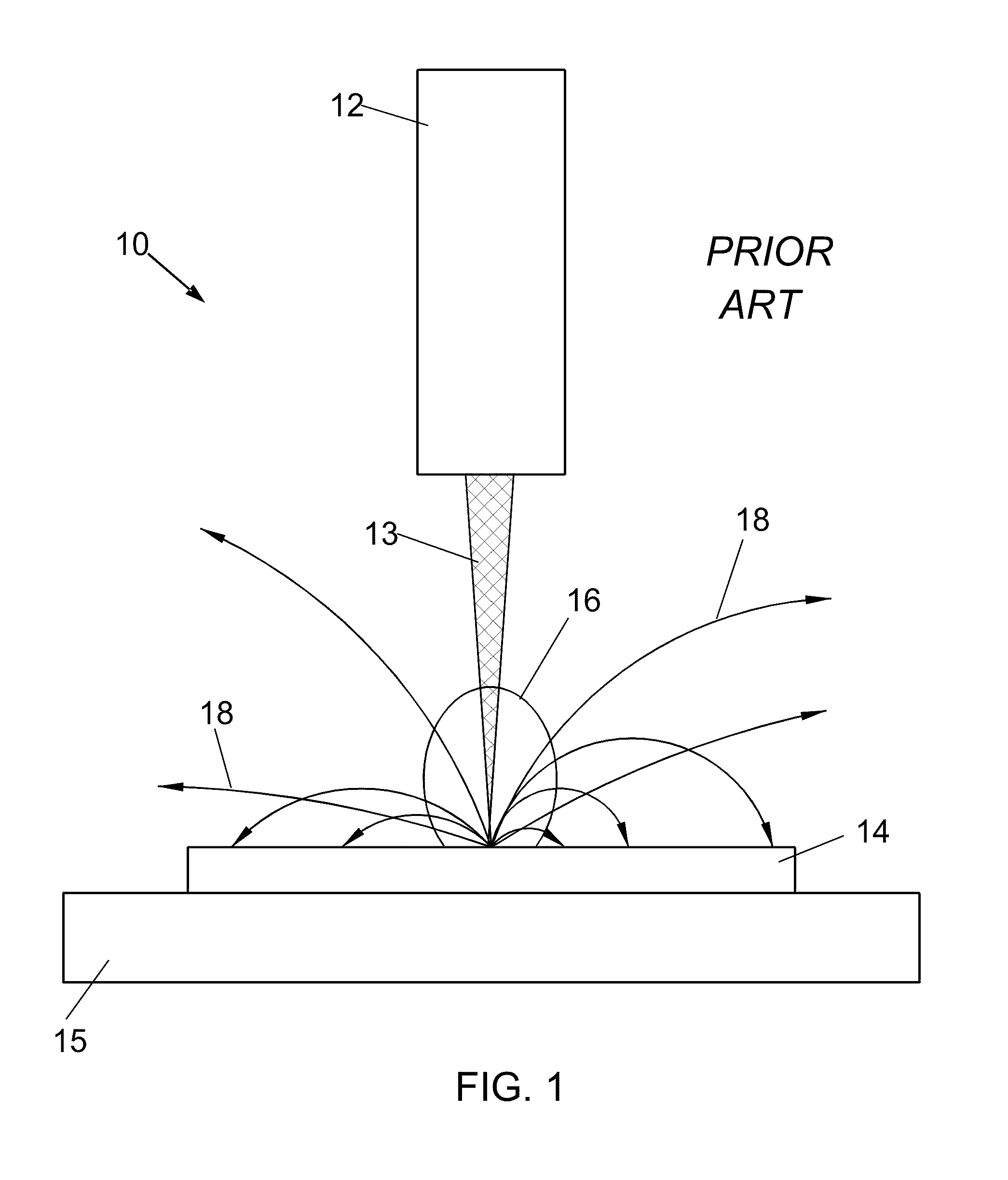
Unfortunately, high-precision milling or sample removal often requires some tradeoffs.
The processing rate of the liquid metal ion source is limited by the current in the beam.
As the current is increased, it is harder to focus the beam into a small spot.
Lower beam currents allow higher resolution, but result in lower erosion rates and hence longer processing times in production applications and in laboratories.
Further, even at higher beam currents, focused ion beam milling may still be unacceptably slow for some micromachining applications.
Thus, while a charged particle beam typically has greater resolution than a laser beam and can micromachine extremely small structures, the beam current is limited and the micromachining operation can be unacceptably slow.
Laser micromachining, on the other hand, is generally much faster, but the resolution is inherently diffraction-limited by the longer beam wavelength.
However, optical fibers cannot be used to deliver ultrashort (i.e., pulses shorter than 10 ps) laser pulses.
This is because weakly coupled single mode fibers compromise the pulse duration due to group velocity dispersion, while single mode fibers that are well coupled to the laser pulses are damaged by the high peak powers achievable by relatively low energy ultrashort pulses.

Method used


Image

  • Combination laser and charged particle beam system
  • Combination laser and charged particle beam system
  • Combination laser and charged particle beam system

Examples


embodiment 300

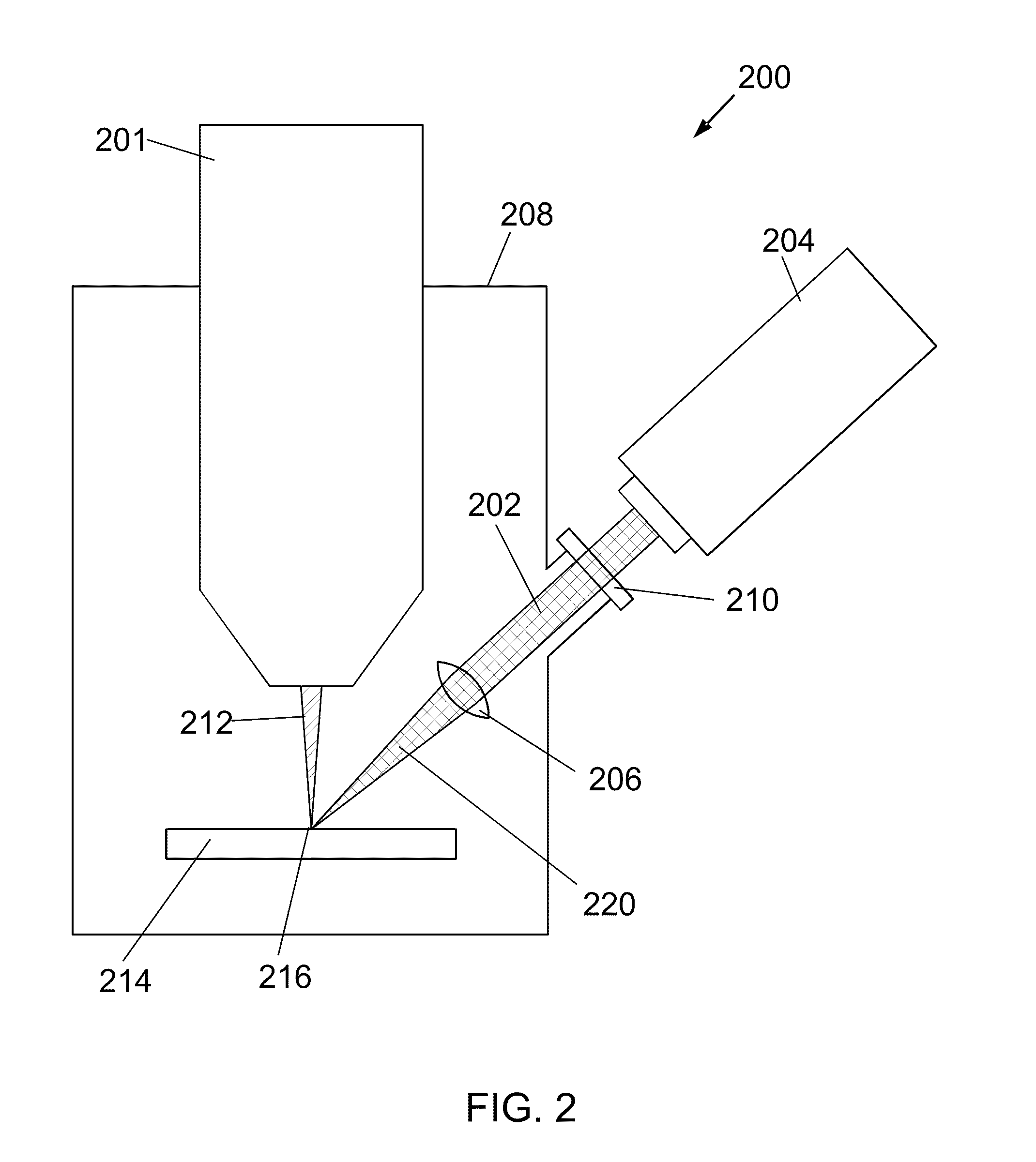
[0053]FIGS. 3A and 3B show a preferred embodiment 300 of the invention comprising a combination dual beam FIB / SEM with a confocal laser. As in FIG. 2, the laser beam 302 from a laser (not shown) is focused by lens 306 located inside the vacuum chamber 308. In the embodiment of FIG. 3, the positioning and focusing of laser beam 302 can be controlled via lens positioning assembly 320 (“LPA”), which can be used to adjust the position (in X, Y, and Z) of the lens 306. A beam generated by a laser can be directed through the LPA window 322 so that it passes through LPA tube 324 and lens 306. Charged particle beams produced by electron beam column 316 and focused ion beam column 317 can be coincident with the laser beam 302 on sample 314.

[0054]LPA 320 is shown 400 in greater detail in FIGS. 4A-4B. The adjustment head 430 of the LPA can be mounted to the outer wall of the vacuum chamber (as shown by dashed line 432). XYZ-positioner 434 can be used to adjust the position of the lens and lens...

embodiment 800

[0058]In another preferred embodiment 800, as shown in FIG. 8, a flat mirror 807 could be located between the source of the charged particle beam 812 (column 801) and the sample 814. Again, mirror 807 would preferably have a hole 805 to allow charged particle beam 812 to pass through the mirror 807 and arrive at the sample 814. In this case, the laser beam 802 (generated by laser 804 and entering chamber 808 through window 810) could be focused by a lens 806 (or by a group of lenses) before reaching the mirror 807. Relative to lens 806 (or group of lenses), mirror 807 would preferably be located between the lens 806 and its focal point at the surface of the sample 814. Thus, the laser beam 802 and the charged particle beam 812 would again be both coaxial and confocal.

embodiment 900

[0059]In the preferred embodiment 900 of FIG. 9, a lens 906 with a hole 915 in it could be located below the flat mirror 907 (also having a hole 905), the lens 906 thus focusing the laser beam 902 (generated by laser 904 and entering chamber 908 through window 910) onto the sample 914 while still allowing the passage of charged particle beam 912 (produced by column 901). This configuration could also make the laser beam 902 and the charged particle beam 912 both coaxial and confocal.


PUM


Abstract

A combined laser and charged particle beam system. A pulsed laser enables milling of a sample at material removal rates several orders of magnitude larger than possible for a focused ion beam. In some embodiments, a scanning electron microscope enables high resolution imaging of the sample during laser processing. In some embodiments, a focused ion beam enables more precise milling of the sample. A method and structure for deactivating the imaging detectors during laser milling enables the removal of imaging artifacts arising from saturation of the detector due to a plasma plume generated by the laser beam. In some embodiments, two types of detectors are employed: type-1 detectors provide high gain imaging during scanning of the sample with an electron or ion beam, while type-2 detectors enable lower gain imaging and endpoint detection during laser milling.

Description

[0001]This application claims priority from U.S. Provisional Application 61 / 321,539, filed Apr. 7, 2010, which is hereby incorporated by reference.TECHNICAL FIELD OF THE INVENTION[0002]The present invention relates to a combination of a laser beam system with a charged particle beam system.BACKGROUND OF THE INVENTION[0003]Charged particle beam systems are used in a variety of applications, including the manufacturing, repair, and inspection of miniature devices, such as integrated circuits, magnetic recording heads, and photolithography masks. Charged particle beams include ion beams and electron beams.[0004]Ions in a focused beam typically have sufficient momentum to micromachine by physically ejecting material from a surface. Because electrons are much lighter than ions, electron beams are typically limited to removing material by inducing a chemical reaction between an etchant vapor and the substrate. Both ion beams and electron beams can be used to image a surface at a greater m...

Claims


Application Information

Patent Timeline
Patent Type & Authority Patents(United States)
IPC IPC(8): H01J37/26H01J37/00H01J3/14
CPCH01J37/226H01J37/244H01J37/28H01J37/3056H01J2237/31749H01J2237/2815H01J2237/2855H01J2237/3174H01J37/08H01J37/06
Inventor STRAW, MARCUSUTLAUT, MARK W.PARKER, N. WILLIAM
Owner FEI CO
Why Eureka
Try Eureka