Power transfer device, power supply device and power receiving device
a power transfer device and power supply technology, applied in the direction of fixed transformers or mutual inductances, variable inductances, inductances, etc., can solve the problems of difficult to make the coupling constant equal to 1, the transformer's energy transfer efficiency also decreases, and the transformer's coupling constant of 1 is not suitable for non-contact power transfer. achieve the effect of improving the transfer efficiency
- Summary
- Abstract
- Description
- Claims
- Application Information
AI Technical Summary
Benefits of technology
Problems solved by technology
Method used
Image
Examples
first embodiment
[0107]Power Transfer Device
[0108]FIG. 2A is an explanatory diagram illustrating a power transfer device according to a first embodiment of the present invention.
[0109]Of two devices 13 and 14 shown in FIG. 2A, the device 13 on the lower side is a stationary device (for example, a desktop personal computer (PC), a ticket gate machine, a card reader etc.), or a device similar to such stationary devices (for example, a laptop PC etc.). On the other hand, the device 14 on the upper side is a mobile device.
[0110]The devices 13 and 14 include, as a primary circuit 100A or a secondary circuit 200B, the coils (or the loop antennas) 110 and 210 according to each embodiment of the present invention, and the capacitances (not shown in the figures) C1 and C2. In addition, the stationary device 13 on the lower side includes, for example, an electronic circuit 130 that has a power supply circuit and an AC power supply adaptor etc. The device 14 on the upper side includes, for example, an electron...
second embodiment
[0114]Power Transfer Device
[0115]FIG. 2B is an explanatory diagram illustrating a power transfer device according to a second embodiment of the present invention.
[0116]Two devices 14 and 15 shown in FIG. 2B are mobile devices.
[0117]The two devices 15 and 14 respectively include, as a primary circuit 100B and a secondary circuit 200A, the coils (or the loop antennas) 110 and 210 according to each embodiment, of the present invention, and the capacitances (not shown in the figures) C1 and C2. In addition, the two devices 15 and 14 respectively include the electronic circuits 130 and 230 that have, for example, a power supply circuit, a power receiving circuit, and a battery. The two devices 15 and 14 are driven by a battery or the like. The coils, the circuit constants of the power supply circuit and the power receiving circuit, and the like; are set to satisfy the above-described Condition 1 and Condition 2, or Condition 3 and Condition 4. Detailed structures of the coils, the power ...
third embodiment
[0152]Power Transfer Device
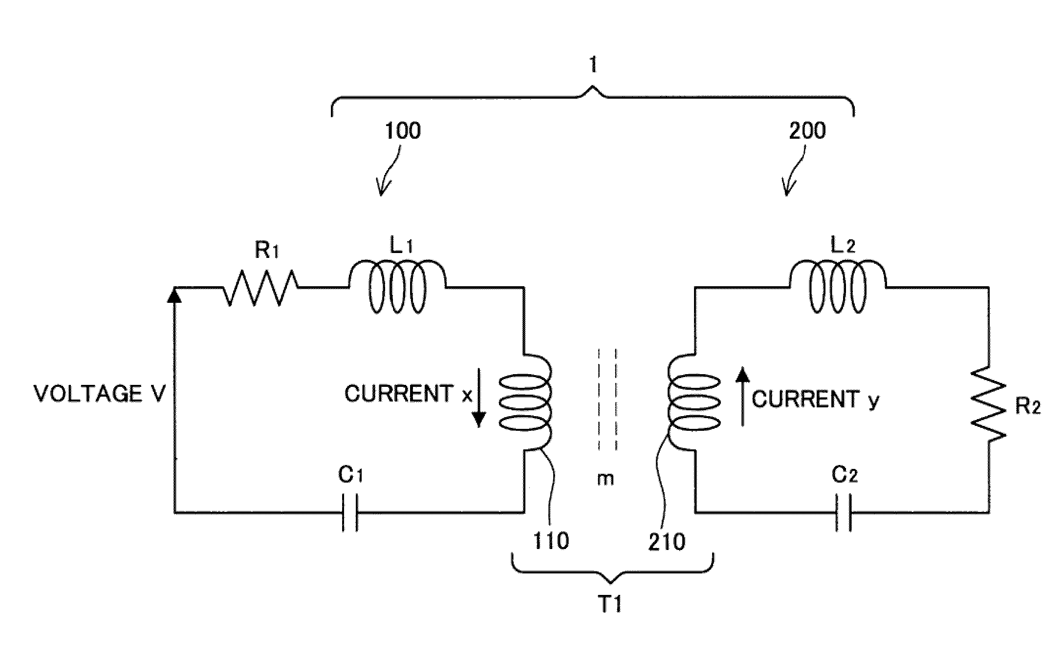
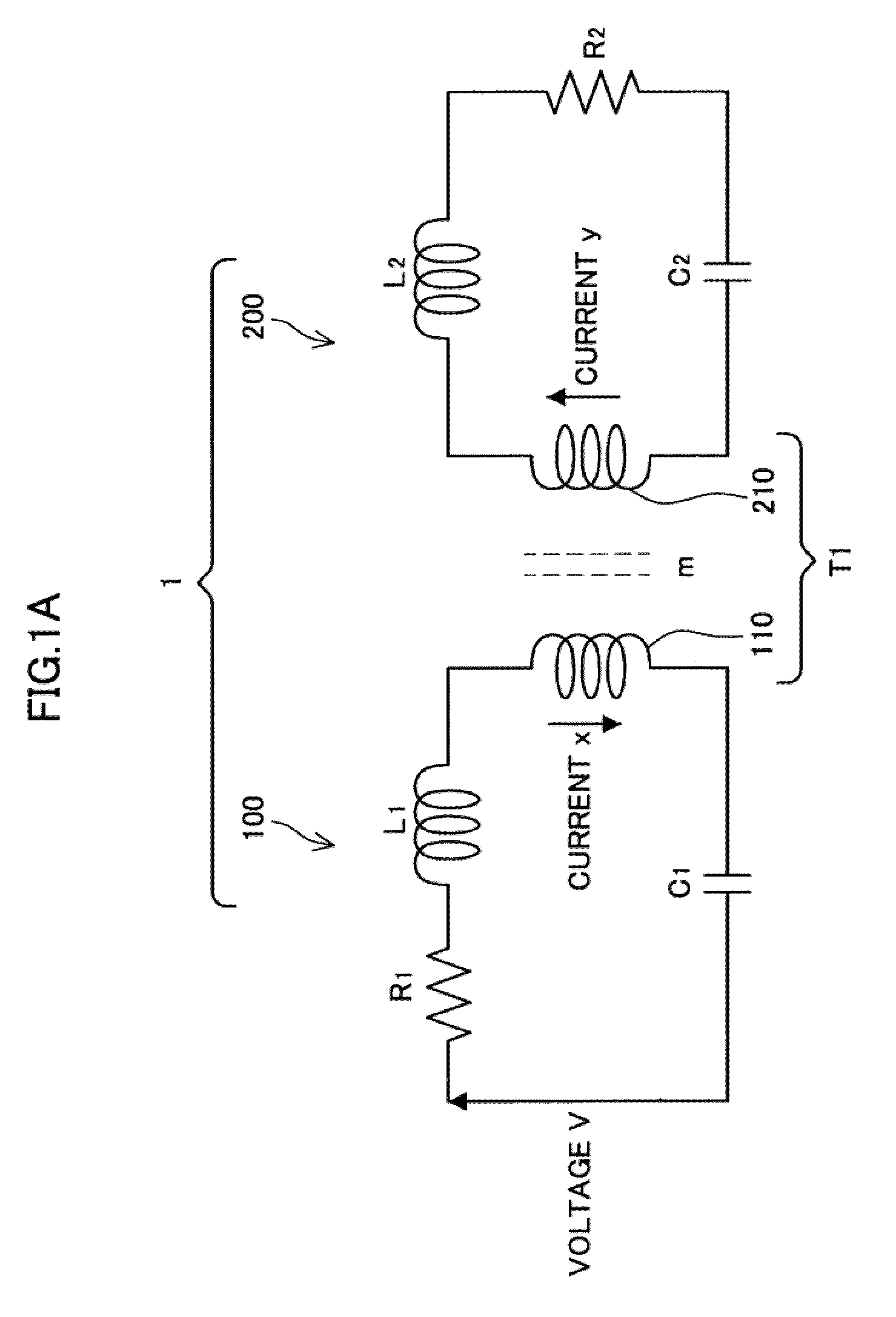
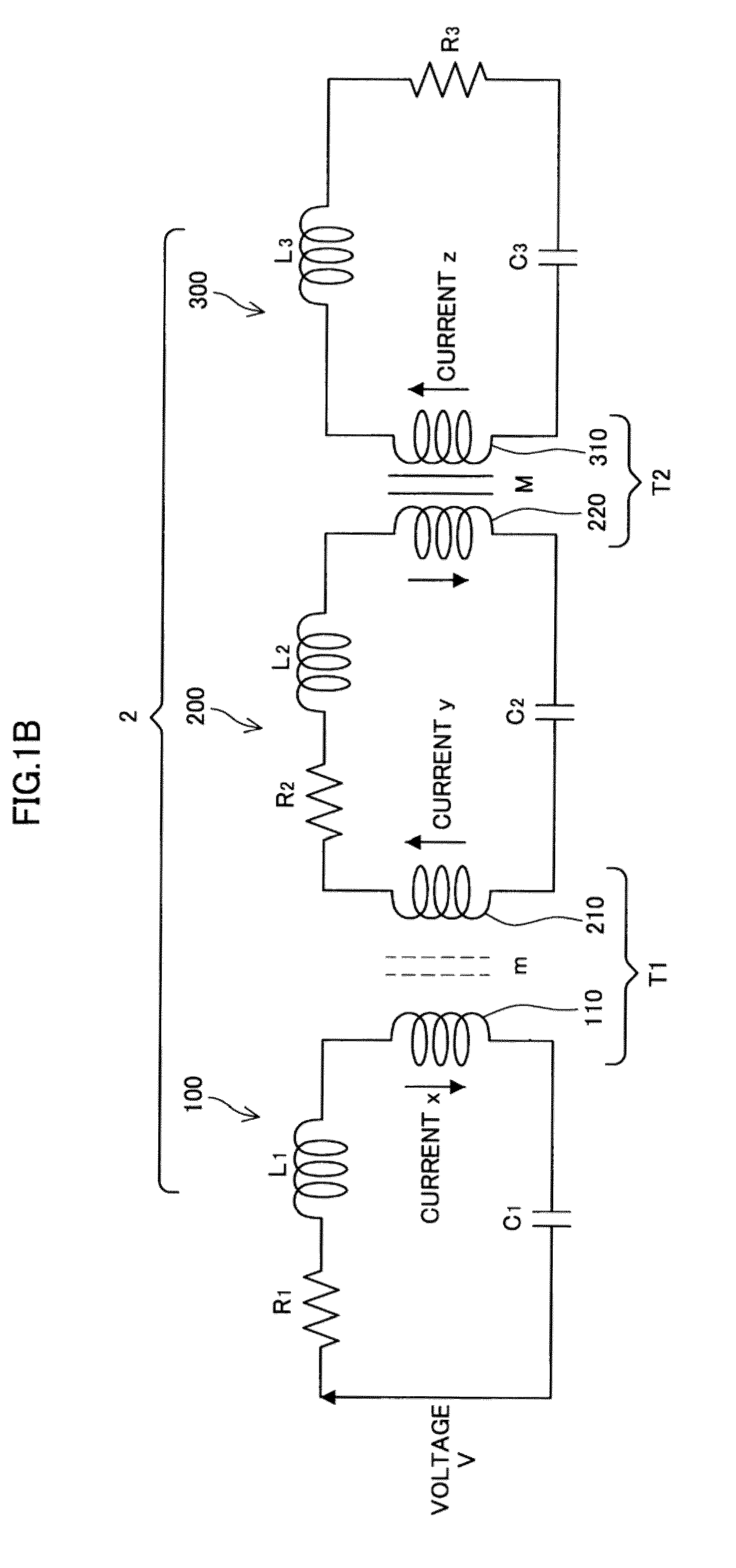
[0153]FIG. 8A is a circuit diagram illustrating a power transfer device according to a third embodiment of the present invention. A primary circuit of a power transfer device 21 is illustrated in the lower section of FIG. 8A, and a secondary circuit is illustrated in the upper section. The primary circuit and the secondary circuit are basically formed as described in, for example, the overview of each embodiment of the present invention, but are different in that the primary circuit includes a particular oscillator circuit as a power supply source. Note that, in the following description, the primary circuit is referred to as a power supply device (a power supply device 100C), the secondary circuit (and a tertiary circuit) is referred to as a power receiving device (a power receiving device 200C).
[0154]As shown in FIG. 8A, the power supply device 100C according to the third embodiment, includes the power transfer coil 110, the resonance capacitance (conden...
PUM
| Property | Measurement | Unit |
|---|---|---|
| resonance frequency | aaaaa | aaaaa |
| length | aaaaa | aaaaa |
| length | aaaaa | aaaaa |
Abstract
Description
Claims
Application Information
 - R&D
- Intellectual Property
- Life Sciences
- Materials
- Tech Scout
- Unparalleled Data Quality
- Higher Quality Content
- 60% Fewer Hallucinations
Browse by: Latest US Patents, China's latest patents, Technical Efficacy Thesaurus, Application Domain, Technology Topic, Popular Technical Reports.
© 2025 PatSnap. All rights reserved.Legal|Privacy policy|Modern Slavery Act Transparency Statement|Sitemap|About US| Contact US: help@patsnap.com


