Photon-alignment optical film

a technology of aligned optical film and film structure, applied in the direction of roads, instruments, traffic signals, etc., can solve the problems of difficult to employ the technology of cholesteric liquid crystal, high manufacturing cost, and easy formation of moiré patterns in the structure of prism-like lenses, etc., to improve the illumination of light, improve the effect of electrical conduction, and high transmittan

Inactive Publication Date: 2012-12-04
S A W GREEN TECH
View PDF8 Cites 7 Cited by
  • Summary
  • Abstract
  • Description
  • Claims
  • Application Information

AI Technical Summary

Benefits of technology

[0013]Another objective of the present invention is that when light travels from a dense medium into a thin medium, the phase of the light is changed by 180 degrees and thus reversed. The phase of transmitting light remains the same, but the reflected light, once subjected to reflection again, is changed to be in phase and the in-phase light passes through the gap passages. In-phase lights from different zones are overlapped to thus enhance the brightness of light.
[0015]A further objective of the present invention is that when core / shell nanoparticles have a size less than full wavelength of visible light, light will not be reflected and thus provide high transmittance and further, the core / shell nanoparticles are of semi-conductivity, and will become excellent in electrical conduction in a lighting environment, thereby providing the characteristics of anti-static.
[0016]Yet a further objective of the present invention is that a center point of the core / shell nanoparticle forms a Poisson spot, where lights from different zones are added due to the same phase to thereby greatly improve the illumination of light, providing a function of convergence similar to a positive lens and providing direction correction for straightforward traveling light when close to the shortest distance of light emission.
[0017]A further objective of the present invention is to provide a photon-alignment optical film, which utilizes the characteristics of catalysis provided by the core / shell nanoparticles. When the core / shell nanoparticles are subjected to light irradiation, pairs of electron and hole having opposite charges and equal electricity are generated. When an external magnetic field is applied, according to Hall Effect, the electrons and the holes are acted upon by Lorentz forces in different directions and thus are respectively gathered in different directions. An electric field is thus established between the gathered electrons and holes. The surfaces of the particles all carry the same polarity. Since there is no conductive wire on the surfaces, no current is induced. According to Lenz's law, here an electric field of electrical current will be induced and according to Ampere's theorem, a magnetic field is also generated, the electric field and the magnetic field being normal to each other and of the same phase and traveling beyond the bond of material to freely prorogate as waves. Within the magnetic field, an electromagnetic force is in action and thus changes the status of the core / shell nanoparticles within a fluid. When all the particles share the same polarity on the surfaces thereof, to cancel the magnetic field between the particles, a new magnetic field is generated, and magnetic pressure induced within the magnetic field causes the particles to move in opposite directions. Such a stress tensor is a second order (r=2) tensor. Thus, the core / shell nanoparticles will reach a distribution in the form of a matrix. This allows the particles to uniformly distribute within an ultraviolet organic plastic material in the form of matrix and the particle, after being subjected to irradiation of light, are set within the organic plastic substance to form a photon-alignment optical film.
[0019]With the above described technology, the above mentioned photon-alignment optical film comprising a core / shell nanoparticle layer shows at least six types of efficacies including high transmittance, anti-static, diffusion, brightness enhancement, effective utilization of light, and correction of travel direction of light. Since a product of the photon-alignment optical film can be done in a single process simply by light irradiation for alignment and ultraviolet irradiation or heating for curing, the manufacturing costs are low and the throughput is high, leading to the advantages of low cost and high market competition power. Thus, the photon-alignment optical film according to the present invention offers the following advantages: (1) anti-static function, (2) transmittance enhancing function, (3) function of high diffusion and high penetration, (4) brightness enhancing function by photocycle overlapping, (5) function of effective utilization of light (polarization), and (6) function of correcting travel direction of light.

Problems solved by technology

This technology shows the following disadvantages: (1) The prism like lens structure is susceptible to the formation of Moiré pattern; (2) Brightness is enhanced in a front view angle, but dark zones, rather than brightness, are formed in side view angles.
However, it is disadvantageous that the stacking and expansion of a thousand of layers of birefringence requires a high manufacturing costs; the stacking adhesion force and the difference in expansion coefficient makes the formation of popcorn during the manufacturing or use, leading the separation of intermediate layers; and rainbow interference color influences color uniformity.
The disadvantages of the cholesteric liquid crystal are (1) formation of elliptical polarization of light so that a phase difference film is needed for further correcting the light to linear polarization of light before it can be used by the liquid crystal; (2) simultaneous effect of R, G, B by the quarter wave film that controls direction, making it difficult to employ the technology of cholesteric liquid crystal and also leading to high costs; and (3) being easily susceptible to temperature change due to the composition of cholesteric liquid crystal.
The disadvantages of this method are as follows: (1) Light leaking zones are present between microstructures, which make it not possible to uniformly diffuse light, eventually leading to non-uniform diffusion of light; and (2) the performance of light diffusion is related to radius of curvature and since it is related to the thickness and cannot be increased, leading to poor performance of diffusion.
(1) Different particle sizes cause uneven reflection and refraction with respect to the optical thickness (¼λ), leading to dispersion of light.
(2) Materials with small difference in high and low refractive indexes makes the performance of diffusion poor.
(3) No light passage is provided, so that light with an angle greater than the critical angle get great loss due to total reflection and thus it provides only optical films of low transmittance.
In view of the above description, it is apparent that the existing optical films all show respective drawbacks, which include poor light diffusion, complication of structure, combined use of various optical film, and high costs.

Method used


Image

  • Photon-alignment optical film
  • Photon-alignment optical film
  • Photon-alignment optical film

Examples


first modified embodiment

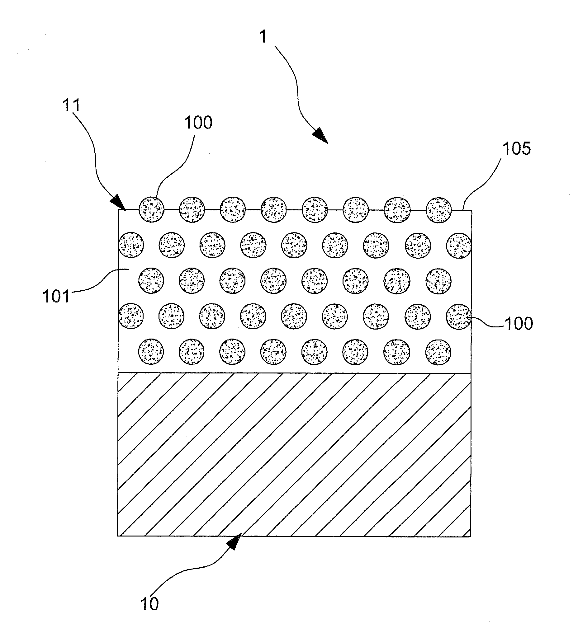
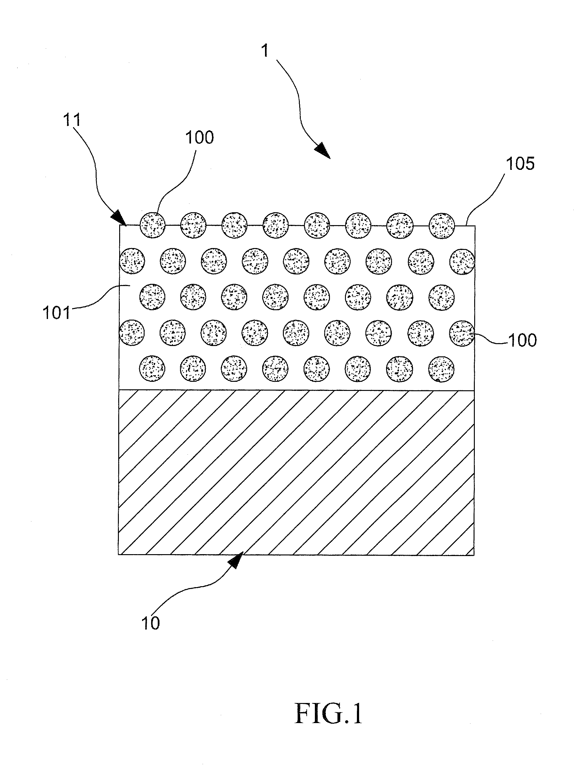
[0073]Referring to FIG. 6, in a first modified embodiment according to the present invention, a photon-alignment optical film, generally designated at 1a, comprises two layers 11, 11a of core / shell nanoparticles and the two core / shell nanoparticle layers11, 11a are applied to sequentially coat on the same surface of a film substrate 10 with a lower layer 11 of the core / shell nanoparticles containing core / shell nanoparticles 100 (referred hereinafter to as “minor particles”) having a size greater than the optical thickness of full wavelength of visible light. The minor core / shell nanoparticles 100 provide functions of light diffusion or brightness enhancement. For anti-reflection or anti-static purposes, the upper layer, namely the outer layer 11a, of the core / shell nanoparticles contains core / shell nanoparticles 100a (referred hereinafter to as “major particles”) having a size less than the optical thickness of full wavelength of visible light.

third modified embodiment

[0074]Referring to FIGS. 8 and 9, second and third modified embodiments of the photon-alignment optic film according to the present invention are shown, both comprising a structure having two layers of core / shell nanoparticles that are arranged opposite to each other, wherein the photon-alignment optical films according to the present invention comprises two layers 11 of core / shell nanoparticle and the two core / shell nanoparticle layers 11 are respectively coated on opposite surfaces of a film substrate 10. One of the core / shell nanoparticle layers contains minor core / shell nanoparticles 100a, while the other layer contains major core / shell nanoparticles 100. In the third modified embodiment, a fraction of the minor core / shell nanoparticles 100a are made protruding beyond an outer surface of the core / shell nanoparticle layer thereof.

second modified embodiment

[0075]Referring to FIGS. 10 and 11, fourth and fifth modified embodiments of the photon-alignment optic film according to the present invention are shown, which, similar to the second modified embodiment discussed previously, comprise a structure having two oppositely arranged layers of core / shell nanoparticles. However, in these two embodiments, the two core / shell nanoparticle layers on the two surfaces both contain minor core / shell nanoparticles 100a, and a fraction of the minor core / shell nanoparticles 100a is allowed to selectively protrude beyond a surface of the associated core / shell nanoparticle layer.

[0076]Referring to FIGS. 12 and 13, sixth and seventh modified embodiments of photon-alignment optical film according to the present invention are shown, wherein a layer of core / shell nanoparticle (comprising minor core / shell nanoparticles 100a) is arranged on a surface of a film substrate 10 and two stacked layers of core / shell nanoparticle (respectively comprising major core / s...


PUM

PropertyMeasurementUnit
optical thicknessaaaaaaaaaa
refractive indexaaaaaaaaaa
thicknessaaaaaaaaaa

Abstract

A photon-alignment optical film includes a film substrate on which at least one layer of core / shell nanoparticles is coated. The core / shell nanoparticle layer includes a plastic substance, which is photo curable or heat curable, and a plurality of core / shell nanoparticles, which is uniformly distributed in the plastic substance. Light energy is used as a driving force to induce electrical potential of the same polarity on the surfaces of the core / shell nanoparticles to make the core / shell nanoparticles rearranged in the form of a matrix due to repulsion induced between like electrical polarity. Spacing between the particles, which is relatively constant, allows light to pass therethrough. The plastic substance is cured by light or heat to have the core / shell nanoparticles set in position to thereby form the optical film. Such an optical film features both diffusion and brightness enhancement.

Description

(a) TECHNICAL FIELD OF THE INVENTION[0001]The present invention generally relates to a film structure, and more particularly to a photon-alignment optical film, which employs the characteristics of photo catalysis of core / shell nanoparticles to have molecules uniformly distributed in a plastic substance due to electrical charges of the same electrical property carried on an outer surface of each core / shell nanoparticle induced by electron-hole pairs that are generated by irradiation of the core / shell particles by visible lights and which employs an internal magnetic field to control the spacing between the core / shell nanoparticles, followed by curing of the plastic substance with light or heat to set the core / shell nanoparticles within the coating layer thereby forming the photon-alignment optical film.(b) DESCRIPTION OF THE PRIOR ART[0002]A Flat Panel Display (FPD) cannot emit light by itself and thus backlighting is needed to provide a light source. Consequently, an optical film p...

Claims


Application Information

Patent Timeline
Patent Type & Authority Patents(United States)
IPC IPC(8): B32B5/16G02B1/10G02B5/02C08J7/044
CPCB82Y20/00C08J7/047G02B5/02Y10T428/2438Y10T428/258Y10T428/24372Y10T428/2991Y10T428/25Y10T428/24413C08J7/0427C08J7/044
Inventor LIN, TIEN-TSAI
Owner S A W GREEN TECH
Why Eureka
Try Eureka