Photo-crosslinked gas selective membranes as part of thin film composite hollow fiber membranes
a composite hollow fiber and photo-crosslinked technology, applied in the field of air separation membranes, can solve the problems of increasing complexity and cost in membrane production, and many commercially available membranes are unsuitable for aircraft applications
- Summary
- Abstract
- Description
- Claims
- Application Information
AI Technical Summary
Benefits of technology
Problems solved by technology
Method used
Image

Examples
example 1
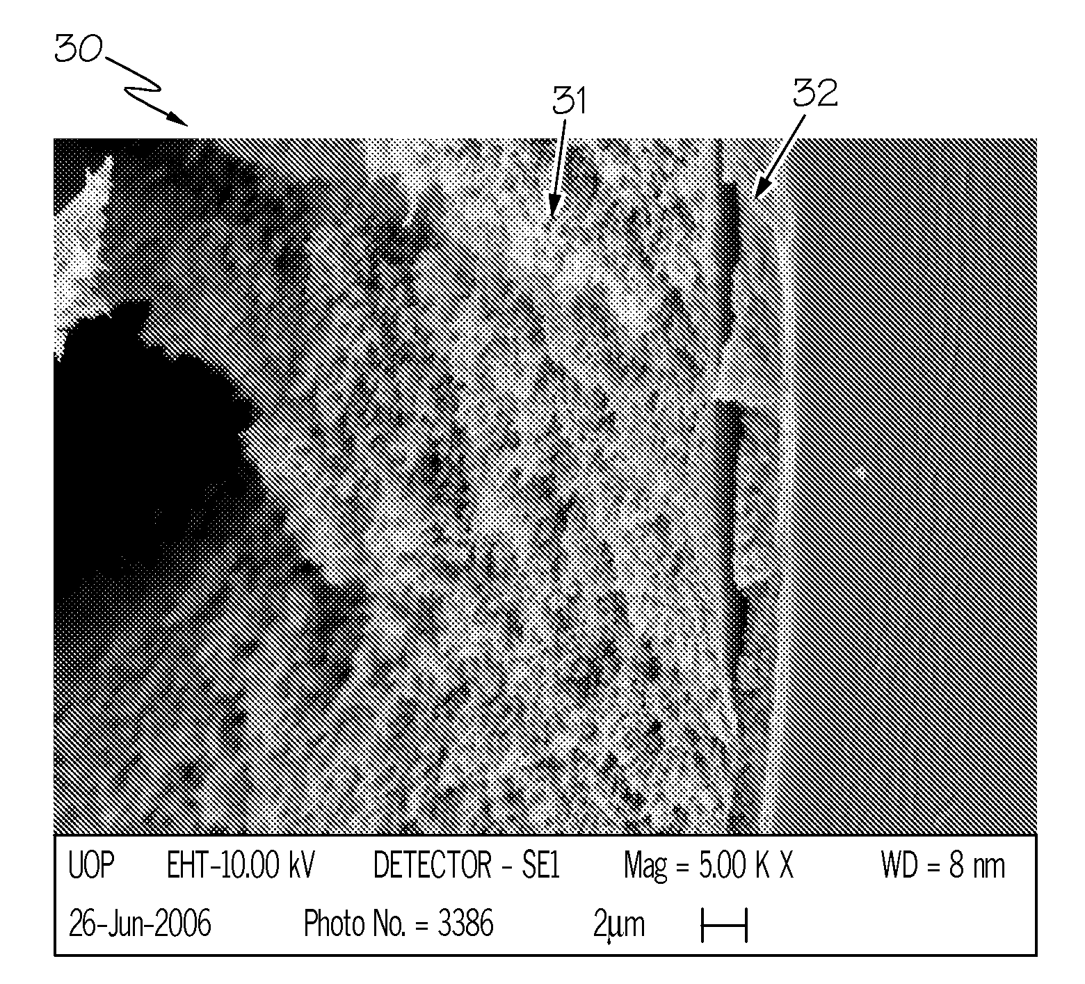
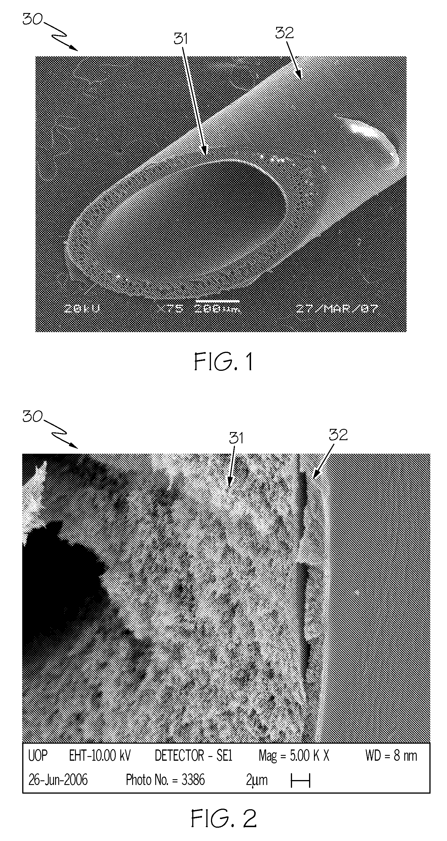
[0050]Thin film composite hollow fiber membranes were cast using Ultem for the core polymer and Matrimid polyimide as the sheath polymer. A table of spinning conditions is shown in Table 2. The SEM image in FIG. 2 shows a gas separation membrane 30 using Matrimid for the sheath layer 32. The photo is of one side of a single hollow fiber, with the central hole visible on the left edge. The bulk of the fiber (core layer 31) is comprised of Ultem, and shows very good morphology with lots of very small pores and few if any large voids. In this photo the core layer 31 is 90 microns thick. The sheath layer 32 is laid on top of this, and appears to be about 2 microns thick. For some embodiments, the thickness of the sheath layer 32 may be between about 0.1 and about 3 microns. Careful inspection shows that the sheath layer 32 is itself asymmetric, with more porosity toward the center of the fiber, and less toward the edge. It can estimate that the actual selective layer may be only 500 nm ...
example 2
[0051]Two solutions are prepared, one for the core layer and one for the sheath layer. The core is Ultem polyetherimide. Alternately, the core may be Ultrason polyethersulfone. The core polymer is typically dissolved in NMP, optionally containing a nonsolvent such as ethanol or triethylene glycol. The sheath polymer is polymer C which is a UV-crosslinkable polyimide synthesized from a mixture of three dianhydride monomers 3,3′,4,4′-benzophenone tetracarboxylic dianhydride, pyromellitic dianhydride, and 4,4′-oxydiphthalic anhydride and one diamine monomer 3,3′,5,5′-tetramethyl-4,4′-methylene dianiline dissolved in a blend of solvents adjusted to be near its solubility limit. NMP is a major component of this solvent, and 1-3-dioxolane, acetone and methanol are also used. The two polymer solutions are forced through a spinneret as described above, into a water bath where coagulation occurs. The resultant fiber is solvent exchanged with methanol and then hexanes, and dried. The resultan...
example 3
[0052]In order to understand the intrinsic gas separation characteristics of some of the polymers used as sheath or core materials, dense film permeabilities were measured. Samples were prepared by dissolving each polymer separately in a volatile solvent, then allowing the solvent to evaporate to make a dense film. A dense film circle with ˜50 μm thickness and 9-10 cm2 testing area was mounted in a dense film testing cell. One face of this film was exposed to air at the indicated pressure in Table 5, while the other face was exposed to a closed vessel which had been placed under vacuum. The rate at which gases permeated the film and therefore increased the pressure inside the vessel was recorded. GC analysis was used to determine the O2 and N2 compositions in the feed air gas and the permeate gas, so that the O2 / N2 selectivity can be calculated.
[0053]Table 5, below, shows that Polymer C dense film without UV treatment provide O2 / N2 selectivity (αO2 / N2)2 / N2 selectivity decreases from...
PUM
| Property | Measurement | Unit |
|---|---|---|
| glass transition temperature | aaaaa | aaaaa |
| temperature | aaaaa | aaaaa |
| temperatures | aaaaa | aaaaa |
Abstract
Description
Claims
Application Information
PatSnap Eureka turns technology decisions into work you can execute. Powered by our Innovation Knowledge Graph, it runs expert workflows across engineering, life sciences, materials and intellectual property. Get your review-ready output in minutes.


